How to control a 4 digit 7 Segment Display from Raspberry PI with Python
Last Updated on 12th April 2024 by peppe8o
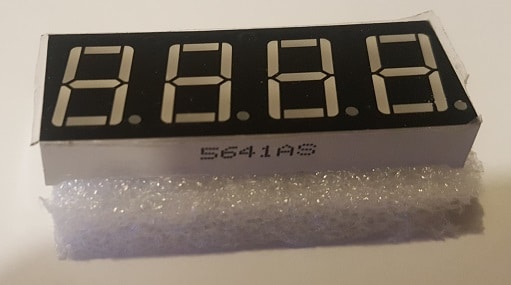
4 Digit 7 Segment Display is a simple electronic display, similar to Single 7 segment display, but composed of 4 digits than can show at the same time 4 chars. It also has dot leds, but in different confiurations (single for each digit, central colon, etc).
4 digit 7 segment display is widely known and used in clock, simple screens and low cost number displaying. Raspberry PI can directly manage it by using proper GPIO connections and a few lines of python code
It is used within a wide number application, usually to diplay time.
Its operation is based on persistence of vision principle: you can drive one digit at time, so you must drive each digit at a speed so that human eye cannot perceive power off moments.
When using 4-digit 7-segment display, please notice that if it is common anode, the common anode pin connects to the power source; if it is common cathode, the common cathode pin connects to the GND. This guide is based on cathode one, nut anode works with the same code by inverting digit selection logic.
These devices have a simple internal wiring diagrams:
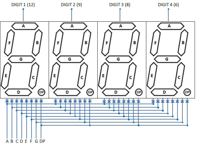
As shown in picture, once configured A…DP pins to 1 (HIGH) to diplay correct number, pins 12, 9, 8 and 6 drive in what digit position to display. For cathode elements, these four pins must all stay to 1 (HIGH) except for the digit you want to power on. For anode elements, these pins must all stay to 0 (LOW) except for the digit you want to power on.
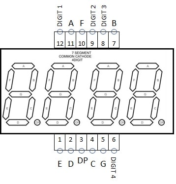
Followin picture shows also the pinout for the cathodic 4 digit display I’m going to use:
In this article we’ll control our 4 Digit 7 segment display from a Raspberry PI Zero W. This article applies also to newer Raspberry PI boards.
What We Need
As usual, I suggest adding from now to your favourite e-commerce shopping cart all the needed hardware, so that at the end you will be able to evaluate overall costs and decide if to continue with the project or remove them from the shopping cart. So, hardware will be only:
- Raspberry PI Zero W (including proper power supply or using a smartphone micro usb charger with at least 3A) or newer Raspberry PI Board
- high speed micro SD card (at least 16 GB, at least class 10)
- Dupont Wiring
- Solderless breadboard
- a 4 digit 7 segment display
- 4x resistors (100 Ohm used)
Many of the listed hardware (except from Raspberry PI Zero W and micro SD Card) can be bought alone or can be also found in the useful Elegoo starter kit.
Step-by-Step Procedure
Wiring Diagram
Prepare cabling according to the following wiring diagram:
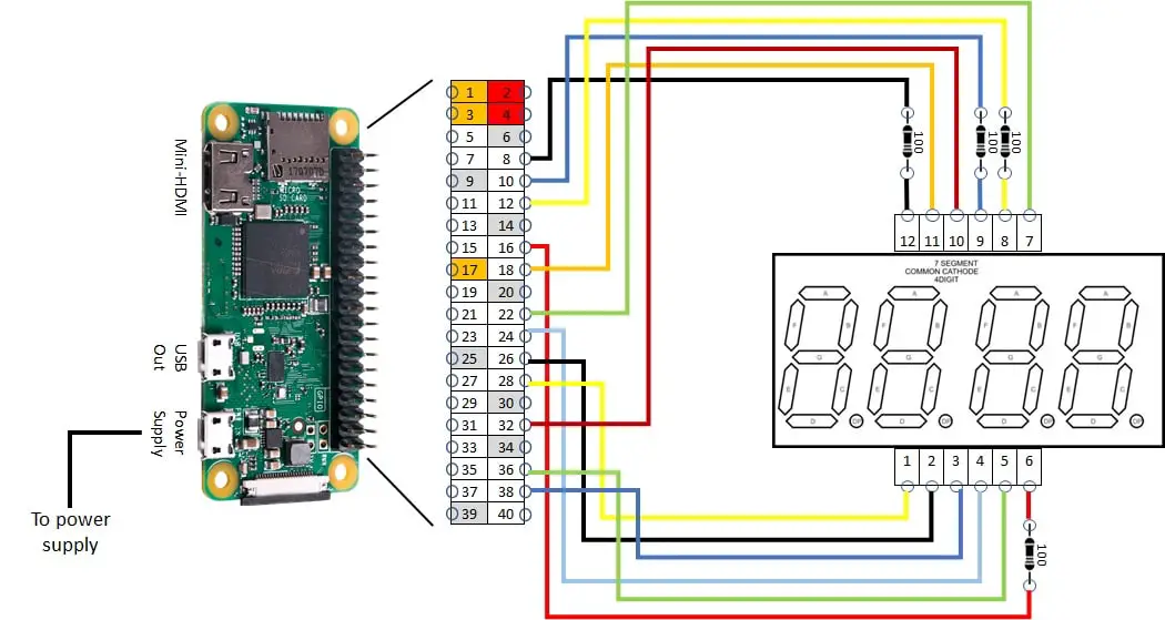
This wiring produces the following mapping between Display and Raspberry PI:
| Display Segment | Display Pin | Raspberry PI physical pin | Raspberry PI BCM GPIO |
| A | 11 | 18 | 24 |
| B | 7 | 22 | 25 |
| C | 4 | 24 | 8 |
| D | 2 | 26 | 7 |
| E | 1 | 28 | 1 |
| F | 10 | 32 | 12 |
| G | 5 | 36 | 16 |
| DP | 3 | 38 | 20 |
| DIGIT 1 | 12 | 8 | 14 |
| DIGIT 2 | 9 | 10 | 15 |
| DIGIT 3 | 8 | 12 | 18 |
| DIGIT 4 | 6 | 16 | 23 |
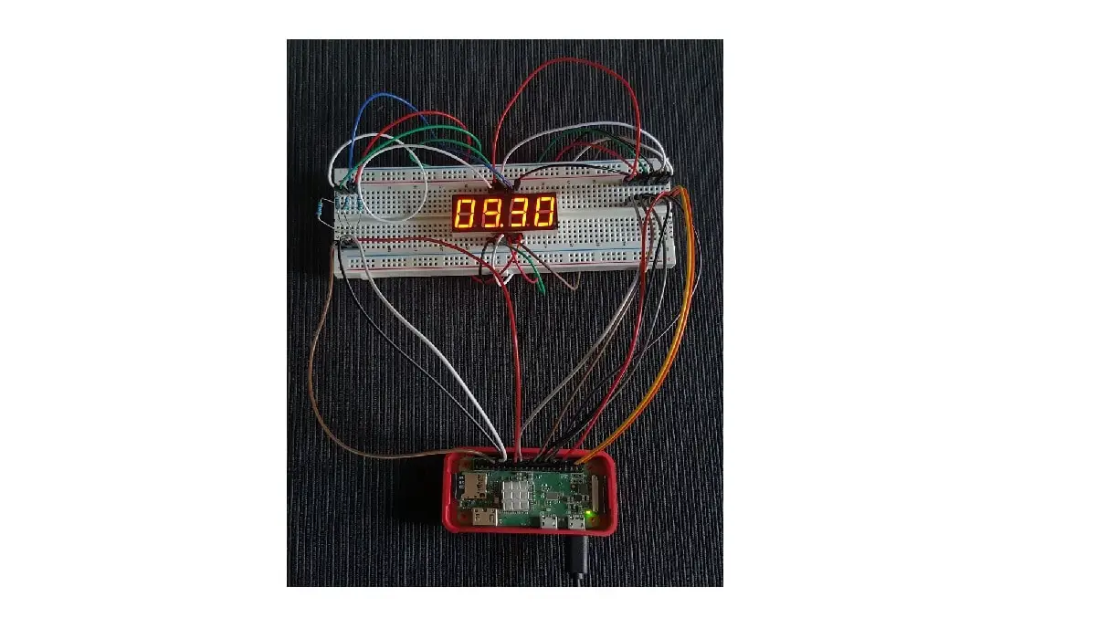
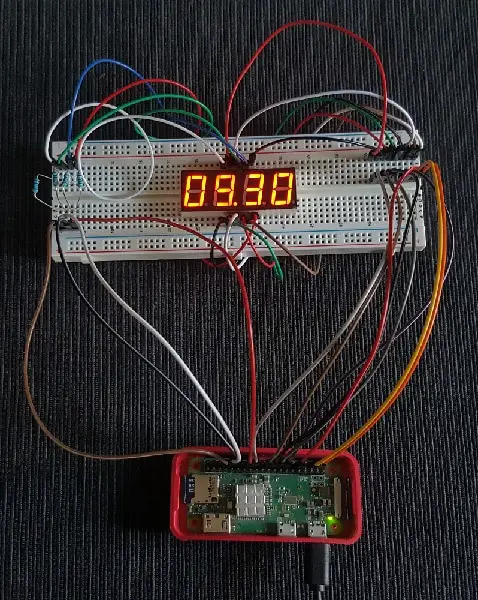
Please find below the overall picture:
OS Preparation
Start with OS installation using Install Raspberry PI OS Lite guide. This guide can be also used with Raspberry PI OS Desktop installation.
Make your OS up-to-date:
sudo apt update
sudo apt upgrade
Python Scripting
RPI.GPIO should be already installed (otherwise, you can get it installed with the command “sudo apt install python3-rpi.gpio”).
Get from my download area seg4DigitDisplay.py script:
wget https://peppe8o.com/download/python/seg4DigitDisplay.pyScript Usage
This script can be used by simply calling from terminal:
python3 seg4DigitDisplay.pyValue to be displayed must be set in “toDisplay” variable inside the script:
toDisplay="16.30" # numbers and digits to displayThis variable can be set with four numbers and one dot or no dot after each number. A space will deploy a powered off digit corresponding to its position. Please find below some valid examples:
- 12.34
- 1.23.4
- 1234.
- 1 2.3 (there is a space between “1” and “2”)
- 1.2 3. (there is a space between “2” and “3”)
- 123. (there is a space before “1”)
- 1.2.3.4.
- 1234
To stop the script, simply press CTRL+C. This will execute a GPIO cleanup closing all GPIOs.
Script explanation
This script starts with some variables set:
toDisplay="16.30" # numbers and digits to display
delay = 0.005 # delay between digits refresh
toDisplay sets what you want to show in your display.
Delay is the time every single digit stays on. So, it also depends on the refresh rate for the overall display. This is an important variable. A too low delay means that Raspberry PI could not be able to disable/enable GPIOs so fast, thus resulting in all segments in all digits appearing on. A too high delay means that refresh rate is affected, resulting in a blinking effect for display digits (with the persistence of vision resulting compromised). Also, resistors affect these results. With 100ohm resistors, I reached a good result on 0.005 seconds delay.
The following section defines what Raspberry PI pins we are going to use. We will use BCM naming convention. Please refer to Raspberry PI Pinout for physical to BCM relations
selDigit = [14,15,18,23]
# Digits:   1, 2, 3, 4

display_list = [24,25,8,7,1,12,16] # define GPIO ports to use
#disp.List ref: A ,B ,C,D,E,F ,G

digitDP = 20
#DOT = GPIO 20
Then GPIOs are also all set as output:
GPIO.setwarnings(False)
for pin in display_list:
 GPIO.setup(pin,GPIO.OUT) # setting pins for segments
for pin in selDigit:
 GPIO.setup(pin,GPIO.OUT) # setting pins for digit selector
GPIO.setup(digitDP,GPIO.OUT) # setting dot pin
GPIO.setwarnings(True)
Warnings are disabled because this script will leave the display active after execution.
An array is prepared to manage easily segments activation for each single number (so that arrSeg[0] shows 0, arrSeg[1] shows 1, etc):
arrSeg = [[1,1,1,1,1,1,0],\
 [0,1,1,0,0,0,0],\
 [1,1,0,1,1,0,1],\
 [1,1,1,1,0,0,1],\
 [0,1,1,0,0,1,1],\
 [1,0,1,1,0,1,1],\
 [1,0,1,1,1,1,1],\
 [1,1,1,0,0,0,0],\
 [1,1,1,1,1,1,1],\
 [1,1,1,1,0,1,1]]
Then the two main functions come. As you can remember, we defined what to display as a string in toDisplay variable. spliToDisplay function splits this string in an array of 4 elements so that each element is a simple number (or space). Also, dots are added to the element that the dot is following.
def splitToDisplay (toDisplay): # splits string to digits to display
 arrToDisplay=list(toDisplay)
 for i in range(len(arrToDisplay)):
  if arrToDisplay[i] == ".": arrToDisplay[(i-1)] = arrToDisplay[(i-1)] + arrToDisplay[i] # dots are concatenated to previous array element
 while "." in arrToDisplay: arrToDisplay.remove(".") # array items containing dot char alone are removed
 return arrToDisplay
With an array so composed, the showDsiplay function takes charge to display all 4 digits. This uses a for cycle with 4 steps. Each step enables a digit by putting its selector to 0 (LOW). This is because we are using a cathode Display.
def showDisplay(digit):
 for i in range(0, 4): #loop on 4 digits selectors (from 0 to 3 included)
  sel = [1,1,1,1]
  sel[i] = 0
  GPIO.output(selDigit, sel) # activates selected digit
  if digit[i].replace(".", "") == " ": # space disables digit
   GPIO.output(display_list,0)
   continue
  numDisplay = int(digit[i].replace(".", ""))
  GPIO.output(display_list, arrSeg[numDisplay]) # segments are activated according to digit mapping
  if digit[i].count(".") == 1:
   GPIO.output(digitDP,1)
  else:
   GPIO.output(digitDP,0)
  time.sleep(delay)
With anode displays modify the two rows according to the following:
 sel = [0,0,0,0]
 sel[i] = 1
Finally, the main loop is an infinite number of recalls to previously defined functions in pipe.
try:
 while True:
  showDisplay(splitToDisplay(toDisplay))
except KeyboardInterrupt:
 print('interrupted!')
 GPIO.cleanup()
sys.exit()
The “except KeyboardInterrup” manages a Keyboard interrupt (CTRL+C) so that this trigger passes a GPIO cleanup before exiting, so powering off the whole circuit.
Enjoy!

Hey,
I modified your code a bit to get it worked for me, basically it is quite similar to what you have achieved so far, but there is some changes in the way of displaying numbers.
I appreciate your efforts to make such nice tutorials.
the code is below:
import sys, os
import RPi.GPIO as GPIO
import time
import random
#fpid = os.fork()
#if fpid!=0:
to_display = ‘12,25’
GPIO.setmode (GPIO.BCM)
GPIO.setwarnings(False)
display_list = [17,27,22,10,9,11,6] #
# display list ref: A, B, C, D, E, F, G
for pin in display_list:
GPIO.setup(pin,GPIO.OUT) # set pins for each segement
# digits 1, 2, 3,4
set_digit = [26,8,19,7] #23=29
for digit in set_digit:
GPIO.setup(digit,GPIO.OUT) # set pins for digit selector
digit_dot = 16
# dot GPIO port
GPIO.setup(digit_dot, GPIO.OUT)
GPIO.setwarnings(True)
# A, B, C, D,E,F,G
arrSeg = [[0,0,0,0,0,0,1],\
[1,0,0,1,1,1,1],\
[0,0,1,0,0,1,0],\
[0,0,0,0,1,1,0],\
[1,0,0,1,1,0,0],\
[0,1,0,0,1,0,0],\
[0,1,0,0,0,0,0],\
[0,0,0,1,1,1,1],\
[0,0,0,0,0,0,0],\
[0,0,0,0,1,0,0]]
def split_num(to_display): # splits the given number string
“”” Splits variable ‘to_display’ string to a list of elements,
so that each element is a simple str number or space, and set strains to number
of digits given
“””
arrToDisplay = list(to_display)
if “,” in arrToDisplay:
arrToDisplay[arrToDisplay.index(‘,’)] = ‘.’
# index “,” inlist and replace with “.”
if len(arrToDisplay) > 5:
raise ValueError(‘Given Number is out of the range of display!’)
# raise error if given number is more that for digits
return arrToDisplay
def show_display(num): # num represents any number that splitTodisplay cleans up
“”” this function basically activates digits and the corresponding display
segements according to the variable(num), and removes ‘.’ from the variable
if it finds one
“””
# handling floating numbers
if len(num) > 4:
for i in range(0,4):
new_num = [x for x in num if x!=’.’] # if ‘.’ in num, replaces ‘.’ with ”
sel_digit = [[1, 0, 0, 0],\
[0, 1, 0, 0],\
[0, 0, 1, 0],\
[0, 0, 0, 1]]
GPIO.output(set_digit,sel_digit[i])
GPIO.output(display_list,arrSeg[int(new_num[i])])
# activate decimal digit
if num[i+1] == ‘.’:
GPIO.output(digit_dot,0)
else:
GPIO.output(digit_dot,1)
time.sleep(.0001)
# integer number
else:
for i in range(0,4):
sel_digit = [[1, 0, 0, 0],\
[0, 1, 0, 0],\
[0, 0, 1, 0],\
[0, 0, 0, 1]]
GPIO.output(set_digit,sel_digit[i])
GPIO.output(display_list,arrSeg[int(num[i])])
time.sleep(.0001)
try:
time_end = time.time()+2 # time.time() time elapsed since 1970 in seconds
# while loop runs only two minutes , not a infinite loop
while time.time()<time_end: # while loop runs for 2 seconds
show_display(split_num(to_display))
except KeyboardInterrupt:
print('interrupted!')
finally:
GPIO.cleanup()
sys.exit()
comments and feedback are always welcomed!
Best wishes,
aVral
Thank you, aVral. I’ll try it as soon as possible
Is there a way to make it display the current time? I’m new to python.
Hi Ethan.
Try changing following code string:
showDisplay(splitToDisplay(toDisplay))with following one:
showDisplay(splitToDisplay(time.strftime("%H.%M")))This uses “strftime” function from time library (already imported) to get current hour and minute into a string format. Remember to maintain same indentantion.
Please, let me know if this works.
Yes tried that and it works fine.
I have a 3 digit display, which there doesn’t seem to be much documentation on it… Is it fairly easy to use this code for that?
Hi Micah. Do you mean that you have a 3-digit display or are you meaning 3x 4-digit displays?
I want to increment the display number by pressing a button. So I added some code to your while loop. It almost works. It will only display the last digit of the numberToDisplay. So when I get to 12, it only displays a 2. And 113, only displays a 3. Any idea why?
Thank you
showDisplay(splitToDisplay(toDisplay))
button.wait_for_press()
#increment
numberToDisplay = numberToDisplay +1
button.wait_for_release()
if numberToDisplay < 10:
toDisplay = " " + str(numberToDisplay)
elif numberToDisplay < 100:
toDisplay = " " + str(numberToDisplay)
elif numberToDisplay < 1000:
toDisplay = " " + str(numberToDisplay)
else:
toDisplay = "" + str(numberToDisplay)
print(toDisplay)
Hi Jason,
comments on HTML pages may not save the right number of consecutive spaces, so I suppose that your code adds 3 spaces before the “str(numberToDisplay)” in the first IF statement, 2 on the second and 1 on the third.
For each numberToDisplay value, do you always see only the last digit powered on? What if you start from numberToDisplay=100?
The very first check I would make will be on cabling.
I’ve followed the plan closely but when I run it my display says 4.5.9.9.
I’m new to Python
Hi Nicolaus,
when the showed number is different from expected it probably means that some cables are not connected to the right PIN. Please double check wiring
Hey! This tutorial was great! Can I know how I can modify the code to display numbers from 1-0 and alphabet from A-Z? As well as maybe a small message like ‘hello’ or something in a loop? I would very much appreciate your response!
Hi. Sorry for the late answer…
Of course you can do it, by defining a custom function instead of arrSeg[] array. The custom function should get as input a single char (string) and give as output a bit array matching the LEDs to power on for that character.
Hope this can still help you