Using mini Switch Button with Raspberry PI and Python
Last Updated on 24th March 2023 by peppe8o

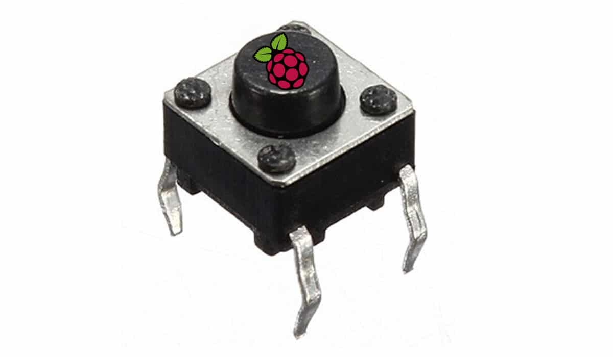
Switch buttons are very simple electronics component. They have simple internal circuit connecting electrically a first PIN with a second PIN on button pression.
Switch button usually have a very low internal resistance. For this reason people usually connect a reading PIN through button to ground instead of reading a positive voltage PIN: in last case you should use resistors to protect your read PIN from current failures.
In its internal circuit, opposite PINs work together, while button pushing creates circuit cross-connection:

This is a bit confusing some people imaging a simple push button with only 2 PIN (instead of 4) connected at button pression.
That said, in this tutorial I’m going to show you how to use a switch button with a Raspberry PI with Python. I’m going to use a RPI Zero W, but this guide works also with other Raspberry PI boards.
What We Need
As usual, I suggest adding from now to your favourite e-commerce shopping cart all the needed hardware, so that at the end you will be able to evaluate overall costs and decide if to continue with the project or remove them from the shopping cart. So, hardware will be only:
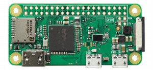
- Raspberry PI Zero W (including proper power supply or using a smartphone micro usb charger with at least 3A) or newer Raspberry PI Board
- high speed micro SD card (at least 16 GB, at least class 10)
- Dupont Wiring
- Solderless breadboard
- Resistors
- LED
- Mini Switch Button
You can find many of this pieces (excluding Raspberry PI and micro SD card) in the good Elegoo kit, which also include other sensors tested in my blog.
Check hardware prices with following links:


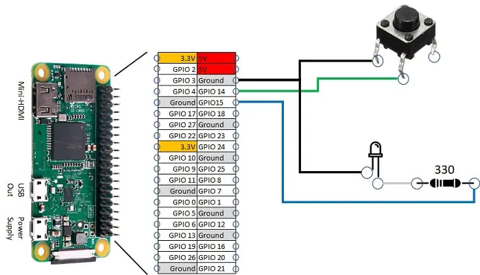
Wiring Diagram
Please find below wiring diagram. We use only 2 of 4 button PINS. One is connected to ground, the other to RPI PIN we’ll read to get button pushing. Note that LED longer PIN (positive) is connected to resistor, than RPI PIN that we’ll activate on button down by python script.
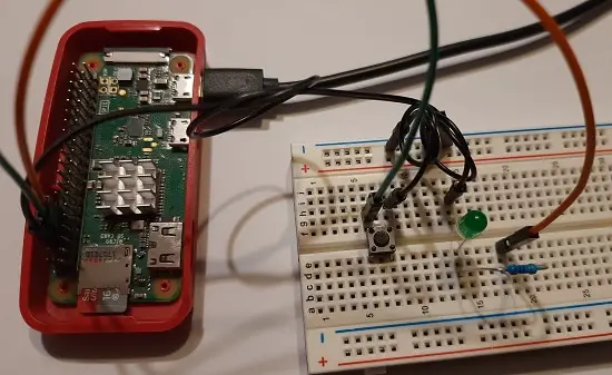
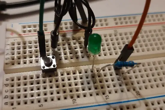
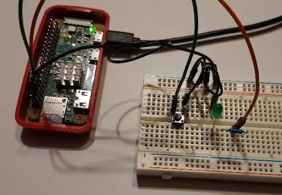
Please find below some pictures on cabling:
Step-by-Step Procedure
Prepare Operating System
Start preparing Operating system for your PI. You can both use install Raspberry PI OS Lite tutorial (for a fast and headless setup, without monitor and keyboard) or install Raspberry PI OS Desktop tutorial (using its internal terminal).
Before starting, please make your OS updated. From terminal:
sudo apt update -y && sudo apt upgrade -yYou don’t need to install Python, as it is already installed in all Raspberry PI OS distros.
RPI.GPIO should be already installed (otherwise, you can get it installed with the command “sudo apt install python3-rpi.gpio”).
Prepare Python Script for Switch Button
I saved my python script in a public area, so that you can download and use it without issues coming from copy-paste operations which could skip some chars (like “#” for comments). Get switch_button.py script from my download area directly in your RPI. From terminal
wget https://peppe8o.com/download/python/switch_button.pyPlease find script explaining below.
Before all, import required libraries:
import RPi.GPIO as GPIOWe associate PIN numbers to variables, for better management. ReadPIN is where we read button state. LedPIN is the one lighting on the LED
readPIN = 14
ledPIN = 15
PINS are setup according to Broadcom naming convention. LedPIN is set to output, as it will drive current to LED. ReadPIN is set to read, as it will read from switch button. Istead of reading 1 (high voltage) when button is pressed, for a safer and simpler circuit we are working with inverted logic:
- when button is pressed, readPIN connects to ground and forced to 0V
- when button is released, readPIN hasn’t an ingress and can read an inconsistent state flapping between high and low reading. We use the RPI internal pull up/down resistors to force read to 1 when an inconsistent state is read
GPIO.setmode(GPIO.BCM)
GPIO.setup(ledPIN,GPIO.OUT)
GPIO.setup(readPIN,GPIO.IN, pull_up_down=GPIO.PUD_UP)
Main program becomes really simple. Remember:
- Case 1: button released -> readPIN to 1 -> ledPIN to 0 -> LED off
- Case2: button pressed -> readPIN to 0 -> ledPIN to 1 -> LED on
this means that ledPIN is always opposite to readPIN, which is implemented in our loop (try/while statements) with following code:
try:
  while True:
    GPIO.output(ledPIN,not(GPIO.input(readPIN)))
Last lines intercept script interruption to send a screen warning of interruption and cleans GPIOs for a correct script ending:
except KeyboardInterrupt:
  print('interrupted!')
  GPIO.cleanup()
Run Script
Run python script with following command from terminal:
python3 switch_button.pyOn button released you will have your LED powered off:
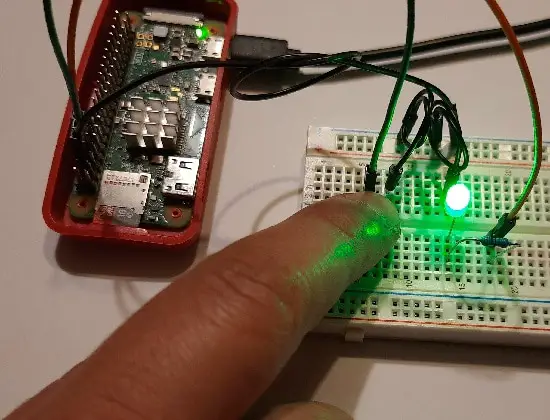
When button is pressed, you will have your LED powered on:
Enjoy!