Using Photoresistor From Raspberry PI To Detect Light
Last Updated on 24th March 2023 by peppe8o
A photoresistor (also known as photocell) is a Light Dependent Resistor (LDR). As the name suggests, these components act just like a resistor, changing their resistance in response to how much light is falling on it. Usually, photoresistors have a very high resistance in near darkness and very low resistance in bright light.
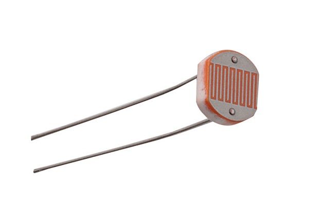
This component is used to manage electronic or electric devices to answer light conditions enabling or disabling functions.
Photoresistors are analogic components. So it can be used with microcontrollers having analogic inputs (like Arduino) to read light level.
Unfortunately, Raspberry PI has only digital inputs (with the threshold between High and Low being around 1V). This means that, without specific analogic-to-digital hardware, we’ll be able only to read if the light is high or low.
In this article, I’ll show you how to use a photoresistor with Raspberry PI and python to detect if the light is high or low. I’ll use a Raspberry Pi Zero W, but this article applies also to newer Raspberry PI boards.
What We Need
As usual, I suggest adding from now to your favourite e-commerce shopping cart all the needed hardware, so that at the end you will be able to evaluate overall costs and decide if to continue with the project or remove them from the shopping cart. So, hardware will be only:
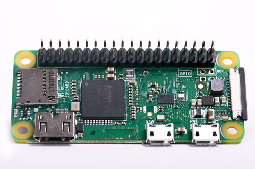
- Raspberry PI Zero W (including proper power supply or using a smartphone micro usb charger with at least 3A) or newer Raspberry PI Board
- high speed micro SD card (at least 16 GB, at least class 10)
- Photoresistor
- NPN Transistor (I used a PN2222)
- resistors
- dupont wiring
- breadboard (optional)
Many of listed hardware (except from Raspberry PI Zero W and micro SD Card) can be bought alone or can be also found in the useful Elegoo starter kit.
Check hardware prices with following links:


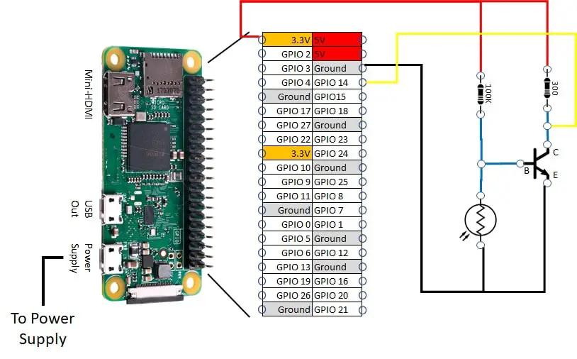
Wiring Diagram
Please find below the wiring diagram to arrange. Please note that VCC+ is connected to a 3,3V port, in order to leave an acceptable voltage entering in reading GPIO (GPIOs can read up to 3,3V, otherwise you risk damaging it):
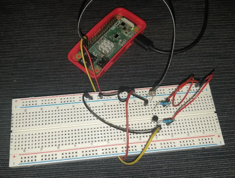
Following picture also shows you my project assembling:
Step-by-step Procedure
Before starting, let’s dig on circuit logic.
Circuit Explaination
This circuit uses a cheap NPN transistor as a switch to enable current passing from the GPIO reading point. As said, photoresistor has an internal resistance that varies depending on light received. In dark conditions, my photoresistor has resistance around 50K ohm. In bright light, my photoresistor has resistance around 500 ohm.
Next schemas will try to simplify concepts. In fact, in analogic world, an NPN transistor will never completely block current. It will more likely get very high resistance levels.
Photoresistor and 100k ohm resistor work together as a Voltage reduction circuit (see also learningaboutelectronics.com: How to Reduce Voltage with Resistors for more details). With low LDR resistance, their middle Voltage level goes down near the ground. It disables the NPN transistor. With high LDR resistance, their middle Voltage level goes up. It enables the NPN transistor.
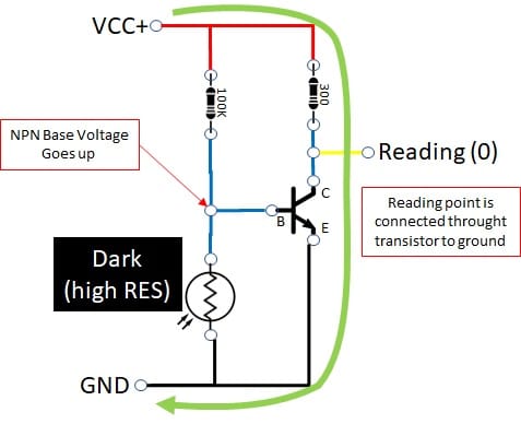
Circuit In Dark Conditions
In dark conditions, the photoresistor increases its internal resistance so increasing voltage at NPN transistor base. This enables the transistor which connects the reading point to the ground. Current flowing from VCC to ground through 300 ohm resistor, GPIO reading point and transistor Collector->Emitter. The final result is a reading point to 0V, so reading a false (0 or low) logic result:
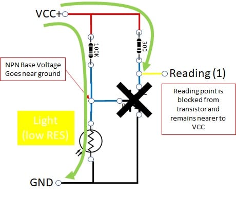
Circuit in Light Conditions
In light conditions, the photoresistor decreases its internal resistance so driving voltage at NPN transistor base near to the ground. This switches off the transistor, which leaves the reading point to VCC level. Current flowing from VCC to ground mainly through 100k ohm resistor and photoresistor. The final result is a reading point near to VCC (3,3V), so reading a true (1 or high) logic result:
Prepare Raspberry PI OS
Install OS with the Install Rasperry PI OS Lite guide. Make your OS up to date. From terminal:
sudo apt update
sudo apt upgrade
RPI.GPIO should be already installed (otherwise, you can get it installed with the command “sudo apt install python3-rpi.gpio”).
Create (or download) Python Script
Python script becomes really simple, as logic is built on hardware. Please download it from my download page with the terminal command:
wget https://peppe8o.com/download/python/photoresistor_rpi.pyand simply run it by typing:
python3 photoresistor_rpi.pyYou can use CTRL+C to stop python script.
The script will start reading “1” in light conditions and reading “0” in dark conditions. It will be enough in a medium illuminated room putting your hand over the upside to create a dark environment:
pi@raspberrypi:~ $ python3 photoresistor_rpi.py
Read: 1
Read: 0
Read: 0
Read: 0
Read: 1
Read: 1
Read: 1
Read: 1
Read: 0
Read: 0
Read: 1
Script is just running following tasks. Needed libraries are imported:
import RPi.GPIO as GPIO
import time
Your read PIN is associated with a specific variable. BCM pin naming will be used. readPIN is set to read (GPIO.IN):
readPIN = 14

GPIO.setwarnings(False)
GPIO.setmode(GPIO.BCM)
GPIO.setup(readPIN,GPIO.IN)
GPIO.setwarnings(True)
The main loop will simply read input PIN and wait 1 second for the next measurement. GPIO reading is converted to string with str() function to concatenate it inside print() function:
print (" Read: " + str(GPIO.input(readPIN)))
time.sleep(1)
Final Toughts
To end, you could need to switch from “0” to “1” result at different light levels. For this purpose, you can try varying the 100k ohm resistor with a lower or higher one until you find light conditions which best fit your needs.
Enjoy!

Unfortunately I always get state 1, even though a LED after transistors shows there is a current when it is dark. But it’s impossible to get voltage small enough on pin 14 with these resistors…
Now I see. The Led was the reason. Everything works now.
Any hints for a python noob… Would like to adapt your script to write output to a log file. Log file entries would only be written when the state changes (from 0 > 1, and from 1 > 0). Plus… entries have to be timestamped. (Am monitoring a thermostat’s LED indicator.) So, log file would look something like:
2022-04-25 20:36:07 1
2022-04-25 20:41:39 0
2022-04-25 20:57:19 1
…
Hi Jon
you must combine my python code with the following:
from datetime import datetimef = open(r"path_to_file.txt","a")# opens the file (a=append, w=write, r=read)now = datetime.now()# current date and timedate_time = now.strftime("%Y-%m-%d %H:%M:%S")#this formats the datetimef.write(date_time+str(GPIO.input(readPIN))+"\n")# the final \n adds a carriage returnf.close()# close the fileThe first import goes at the beginning of code.
The f.open() goes just after importing the libraries.
The third part goes in the “while True:” loop.
The f.close() goes in the “except KeyboardInterrupt:” part.
Please let me know if this works.
Giuseppe
You better to select resistor 100K based on photo resistor resistance. I added a potentiometer to adjust the sensitivity. I used a 30K resistor instead of 100K in series with a 100K potentiometer. Now it works well. For raspberry pi zero, logic level low is less than 1.4V.
Thanks for your information.
Sorry for the late reply and thank you very much for your feedback, Mohammad!