
In this tutorial, we will be making an automatic irrigation system (AIS) with Arduino and the use of temperature, soil moisture and ultrasonic sensors. Based on the water level of the tank, temperature and moisture of the soil an automatic irrigation system is designed to keep the soil moisture.
Introduction
In the irrigation system, normally we have issues with the soil moisture, the water tank empty with water and high temperature. So in this work, a smart irrigation system is being designed which will deal with these two parameters, temperature and soil moisture. These two prominent factors are measured through the sensors and based on the requirement take action to pump the land. But before that have to measure the level of the water in the tank from where the water is coming out.
Working Principle of the Automatic Irrigation System
This innovative automatic irrigation system works based on sensors which continuously measure the water level, and keep focus on the temperature and moisture of the soil. Case-1 the water level is full and soil moisture is low, the pump turns on to give water supply to the soil. Case-2 the water level is full and the temperature high, the pump turns on to give water supply to the soil. Case- 3 the water tank has limited water and soil moisture gets low or temperature becomes high, so the water pump doesn’t turn on.
What We Need

As usual, I suggest adding from now to your favourite e-commerce shopping cart all the needed hardware, so that in the end you will be able to evaluate overall costs and decide if continue with the project or remove them from the shopping cart. So, hardware will be only:
- Arduino Uno Board
- Dupont wirings
- Soil moisture sensor
- Ultrasonic sensor
- Temperature sensor
- LCD
- Pump
- Breadboard
Step-by-Step Procedure
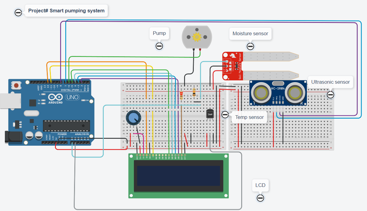
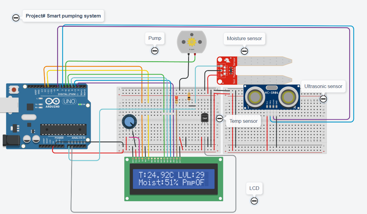
Wiring Diagram of Irrigation system
The sensors, LCD and pump require these connection pins to connect to the microcontroller as given in the table. The pin 1 for each component starts from the left side for convenience.
| Ultrasonic sensor | Arduino | Pump | Soil Moisture sensor | Temperature sensor | LCD |
|---|---|---|---|---|---|
| VCC (PIN 1) | 5 V | VCC | VCC (left) | VCC Pin 2 | |
| Trig (Pin 2) | Pin 7 | ||||
| ECHO (Pin 3) | Pin 8 | ||||
| GND (Pin 4) | GND | GND | GND | GND | R/W (Pin 5) |
| Pin 6 | Pin 2 | A0 (through a resistor) | A1 | ||
| Pin 12 | Pin 4 Register select | ||||
| Pin 11 | Pin 6 en | ||||
| Pin 5 | Pin11 D4 | ||||
| Pin 4 | Pin 12 D5 | ||||
| Pin 3 | Pin 13 D6 | ||||
| VCC | VEE Pin3 (Potentiometer) | ||||
| GND | En (pin 5) | ||||
| Pin 2 | Pin 14 D7 | ||||
| VCC | Pin 15 LED + | ||||
| GND | Pin 16 LED – | ||||
| GND | Pin 1 GND |
Please find below a picture showing the vibration sensor and Arduino Uno wiring diagram:
Get the code for the irrigation system
Connect your PC to Arduino and open Arduino IDE. For the very first steps, you can refer to the Connecting Windows PC with Arduino tutorial. You can get the .ino code from my download area with the following link:
Code Explanation
Section 1: Before setup
In this section, we attach the pump, temperature sensor, moisture sensor, ultrasonic sensors and LCD pins. The threshold for each case limit is defined to compare it during the system work. It is convenient to see the limits at the start of the code to change it with time.
#include <LiquidCrystal.h>
LiquidCrystal lcd(12, 11, 5, 4, 3, 2);

const int pumpPin = 6;
const int temperatureSensorPin = A1;
const int moistureSensorPin = A0;
const int ultrasonicTrigPin = 7;
const int ultrasonicEchoPin = 8;

const int temperatureThreshold = 25;     // Temperature threshold in Celsius
const int moistureThreshold = 20;        // Moisture threshold
const int tanktotalheight = 100;     // Water level threshold (adjust as needed)
const int waterDistanceThreshold = 80;   // Water distance threshold in centimeters
Section 2: In the setup
In the setup, we set the baud rate of the serial monitor to 9600. Then, we initialised the sensor pin, and pump and displayed the “peppe8o.com” on the first line, while the pumping system was on the second line. At the end cleard the screen to display more.
void setup() {
  lcd.begin(16, 2);
  pinMode(pumpPin, OUTPUT);
  pinMode(ultrasonicTrigPin, OUTPUT);
  pinMode(ultrasonicEchoPin, INPUT);
  lcd.setCursor(0, 0);
  lcd.print("peppe8o.com");
  lcd.setCursor(0, 1);
  lcd.print("Pump System");
  delay(2000);
  lcd.clear();
}
Section 3: Loop section
This is the section for the main loop.
The code measures continuously the temperature, moisture level of the soil and the water level of the tank. The temperature pin is connected to the analogue input, we mapped the moisture level to a percentage and measured the water distance with the ultrasonic sensor. To show the result, LCD is displayed, to print the value of each measurement for monitoring.
void loop() {
  float temperature = -40 + 0.488155 * (analogRead(temperatureSensorPin) - 20);
  int moistureLevel = analogRead(moistureSensorPin);
  moistureLevel = map(moistureLevel, 0, 1023, 0, 100);

  // Read water distance from ultrasonic sensor
  long duration, distance;
  digitalWrite(ultrasonicTrigPin, LOW);
  delayMicroseconds(2);
  digitalWrite(ultrasonicTrigPin, HIGH);
  delayMicroseconds(10);
  digitalWrite(ultrasonicTrigPin, LOW);
  duration = pulseIn(ultrasonicEchoPin, HIGH);
  distance = duration * 0.034 / 2;

  lcd.setCursor(0, 0);
  lcd.print("T:");
  lcd.print(temperature);
  lcd.print("C ");
  lcd.print("LVL:");
  lcd.print(tanktotalheight-distance);
  lcd.setCursor(0, 1);
  lcd.print("Moist:");
  lcd.print(moistureLevel);
  lcd.print("%");

  delay(1000); // Adjust delay according to your needs
  lcd.clear();
At this stage, we control the pump based on the comparison of the values to the predefined threshold of temperature, moisture level and water distance. In the case of the condition met or exceeded the threshold the pump gets activated otherwise it remains turned off. The status of the pump gets displayed on the LCD when it gets turned ON or OFF.
// Control pump based on conditions
if (temperature > temperatureThreshold || moistureLevel < moistureThreshold || distance > waterDistanceThreshold) {
// Conditions met, turn on pump
digitalWrite(pumpPin, HIGH);
lcd.setCursor(5, 0);
lcd.print("Pump ON ");
} else {
// Conditions not met, turn off pump
digitalWrite(pumpPin, LOW);
lcd.setCursor(5, 0);
lcd.print("Pump OFF");
}
delay(1000); // Adjust delay according to your needs
lcd.clear();
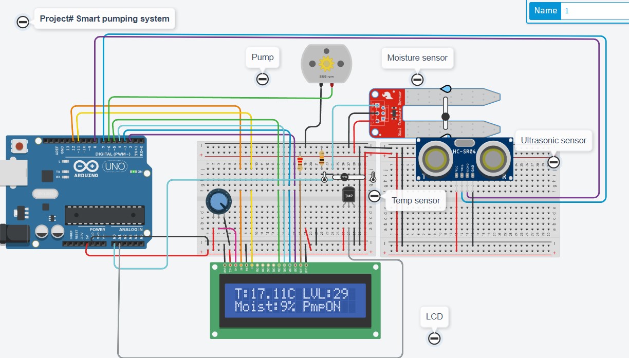
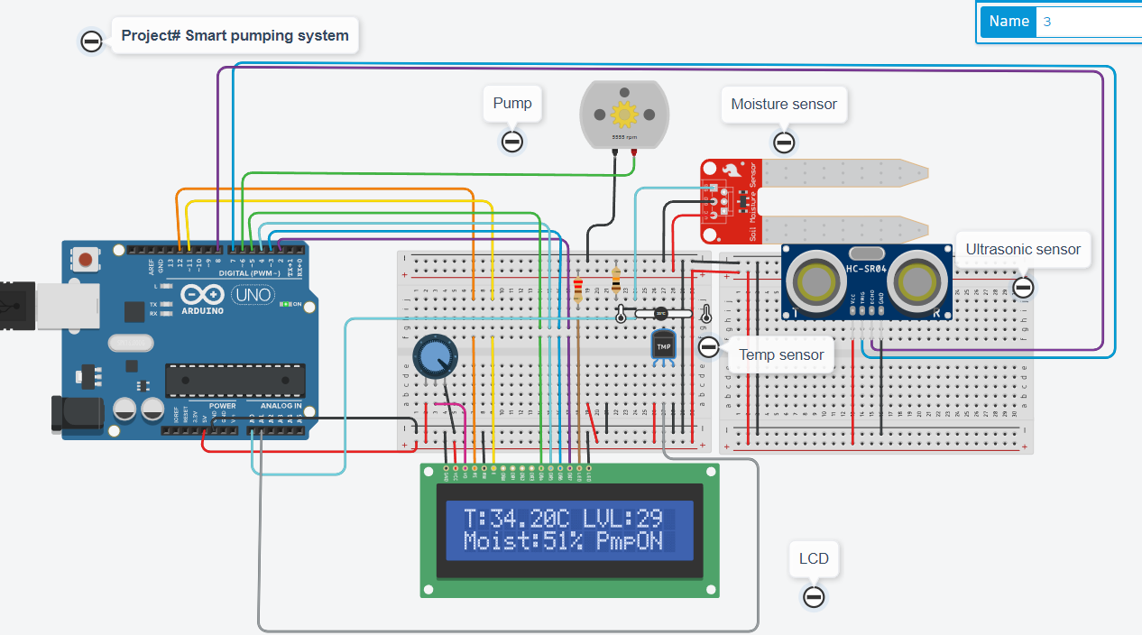
}Results
The results demonstrate the condition of the temperature and the normal case when the temperature increases and the tank is available with the water then the pump turns on to moist the soil. The pump stops when the temperature is reduced to the limit.
What’s Next
Please find more tutorials on Arduino in peppe8o Arduino archives.
Enjoy!
Umar Jamil
For any queries and help with work, please contact me at:
Whatsapp: +92-346-661-7017/ Link Fiverr for order custom work
Email: umarjamil0007@gmail.com

I'm an Electronic Engineer, well-skilled to solve the issues of hardware and software. I do have laboratory which contains unlimited sensors and modules for testing the working. Also, I am experienced in Arduino programming, Android mobile application, microcontroller programming, IOTs and embedded projects. I provide services to control, realize the sensor data in the Mobile Application. For any queries and help for work Contact: Whatsapp:+92-346-661-7017 Email: umarjamil0007@gmail.com
![]()


