
Last Updated on 19th April 2024 by peppe8o
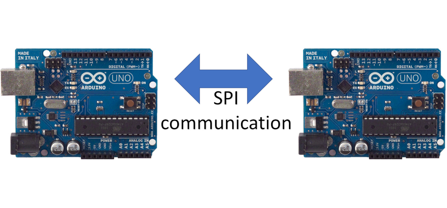
In this tutorial, we will use two Arduino Uno to demonstrate the Serial Peripheral Interface (SPI) communication between them. Each Arduino comes with dedicated pins for the SPI to communicate between the microcontrollers and the other devices.
Introduction
The SPI is a synchronous serial communication protocol which deals with the sharing of data between the two devices: a master and a slave. The defined PINs for the SPI communication are defined as Master Out slave in (MOSI), Master in slave out (MISO), clock (SCK) and Slave Select (SS). In the data, sharing can be performed based on the selection of the device through the SS pin. The device gets selected by pulling the SS line low.
The data shifts out from the master and is shared with the slave with the synchronized clock. The SPI is a full duplex, so it can receive and send data in both directions: the shift register is used to transmit the data from one device to another.
Working Principle of the SPI between two Arduinos
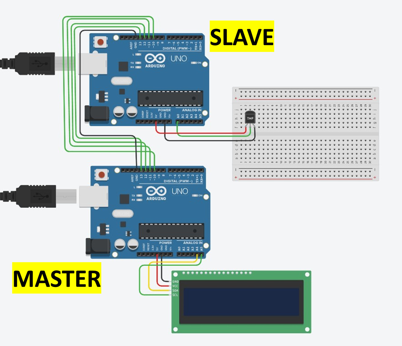
The SPI communication between two Arduinos, one acts as the master while the other is the slave. For the SPI communication, the MOSI of the master connects with the MOSI of the slave Arduino, master MISO with the slave MISO, similar to the SCk with SCK and SS with SS. For Arduino Uno the SPI dedicated pins are SS 10 MOSI 11, MISO 12 and SCK 13.
What We Need

As usual, I suggest adding from now to your favourite e-commerce shopping cart all the needed hardware, so that in the end you will be able to evaluate overall costs and decide if continue with the project or remove them from the shopping cart. So, hardware will be only:
Step-by-Step Procedure
Wiring Diagram of SPI communication
The wiring connections between the two Arduino for SPI communication are presented here.
| Master Arduino | Slave Arduino | Temperature sensor | LCD |
|---|---|---|---|
| SS Pin 10 | SS Pin 10 | ||
| MOSI pin 11 | MOSI pin 11 | ||
| MISO pin 12 | MISO pin 12 | ||
| SCK 13 | SCK 13 | ||
| GND | GND | GND (Pin 3) | GND |
| VCC | Vcc (Pin 1) | ||
| A0 | Aanalogue (Pin 2) | ||
| VCC | VCC | ||
| A4 | SDA | ||
| A5 | SCK |
Please find below a picture showing the 2 Arduino Uno wiring diagram:
Note: Top and lower Arduino are slave and master respectively.
Get the code for the SPI communication between two arduinos
Connect your PC to Arduino and open Arduino IDE. For the very first steps, you can refer to the Connecting Windows PC with Arduino tutorial. You can get the .ino code from my download area with the following link:
Code Explanation
Master:
Section 1a: Before setup
In this section, the I2C library for 16X2 LCD initializes, the SPI pins of MOSI, MISO, CLOCK and chip_select are defined.
The strings for storing the temperature values and the flag of the “newdatareceived” variable are defined too:
#define MISO 12
#define MOSI 11
#define PIN_CLOCK 13
#define CHIP_SELECT 10

#include <Wire.h>
#include <LiquidCrystal_I2C.h>
#define LCD_ADDRESS 0x27
#define LCD_COLUMNS 16
#define LCD_ROWS 2

LiquidCrystal_I2C lcd(LCD_ADDRESS, LCD_COLUMNS, LCD_ROWS);

int receivedTemperature;
bool newDataReceived = false;
Section 1a: Before setup
In this section, the setup_pin function deals with the configuration of the SPI pins direction to set as MOSI, CLOCK, chip_select as the output pins and MISO pin as input.
The readPin deals with the state of a pin and returns a boolean value to acknowledge the value.
The receive_byte function receives data of byte size from SPI. It collects one by one bit and then assembles them in one byte.
The receive_data() function will make use of the receive_data_byte() to set both the temperature value and the boolean newDataReceived:
void setup_pins()
{
  DDRB &= ~((1 << 2) | (1 << 3) | (1 << 5));
  DDRB |= (1 << 4);
  DDRD = (0 << 2) | (0 << 3);
}

bool readPin(int pin)
{
  return PINB & (1 << (pin - 8));
}

byte receive_byte()
{
  byte receivedByte = 0;
  for (int i = 0; i < 8; i++) {
    while (!readPin(PIN_CLOCK));
    receivedByte |= readPin(MOSI) << (7 - i);
    while (readPin(PIN_CLOCK));
  }
  return receivedByte;
}

void receive_data() {
  byte highByte, lowByte;
  if (!readPin(CHIP_SELECT)) {
    highByte = receive_byte();
    lowByte = receive_byte();
    receivedTemperature = (highByte << 8) | lowByte;
    newDataReceived = true;
  }
}
Section 1c: In the loop
In the setup, the baud rate is set to 9600 for the serial monitor and then the code calls the setup pin function. The LCD initialize and turns on the backlight for the LCD. Then, LCD display function will print the values.
void setup() {
  Serial.begin(9600);
  setup_pins();
  lcd.init();
  lcd.backlight();
  lcd.display();
}
Section 1d: In the loop
In the loop, the code calls the receive_data function and keeps on collecting the incoming data.
The new data collects and then displays the collected temperature on the serial monitor as well as on the LCD.
Finally, the flag of the new data received is set to false to make it receive the next data.
void loop() {
  receive_data();
  if (newDataReceived) {
    Serial.print("Received current temp: ");
    Serial.print(receivedTemperature);
    Serial.print(char(176));
    Serial.println("C");
    lcd.clear();
    lcd.setCursor(0, 0);
    lcd.print("Temperature:");
    lcd.setCursor(0, 1);
    lcd.print(receivedTemperature);
    lcd.print(char(176));
    lcd.print("C");
    newDataReceived = false;
  }
}
Slave:
Section 2a: Before setup
This is the section, where the code deals with the SPI communication initialization and defines the float step variable for the ADC.
The setup_pins function deals with the configuration of the SPI pins direction to set as MOSI, CLOCK, chip_select as the output pins and MISO pin as input.
The function start_transmission() sets the CS/SS PIN based on the provided slave_pin number. This prepares the communication channel between the master and the slave device.
#define MISO 12
#define MOSI 11
#define PIN_CLOCK 13
#define CHIP_SELECT 10

float stepADC = 0.0048828125;

void setup_pins() {
  DDRB |= (1 << MOSI) | (1 << PIN_CLOCK) | (1 << CHIP_SELECT);
  DDRB &= ~(1 << MISO);
}

void start_transmission(int slave_pin) {
  PORTB &= ~(1 << (slave_pin - 8));
}
Section 2b: Before setup
At this stage, we define the “stop_transmission” function which deals with the finalization communication with a master by raising the SPI pin high.
The “send_byte” function sends a byte of data to the master.
The clock cycle keeps on generating the spi communication pulse by toggling the clockpin high and low with the right time.
The “send_data_int()” function manages sending 16-bit integer versus SPI by sending the low and high byte separately.
void stop_transmission(int slave_pin) {
  PORTB |= (1 << (slave_pin - 8));
}

void send_byte(byte dataByte) {
  for (int index_bits = 0; index_bits < 8; index_bits++) {
    bool current_bit = dataByte & (0x80 >> index_bits);
    digitalWrite(MOSI, current_bit);
    clock_cycle();
  }
}

void clock_cycle() {
  PORTB |= (1 << (PIN_CLOCK - 8));
  delayMicroseconds(10);
  PORTB &= ~(1 << (PIN_CLOCK - 8));
  delayMicroseconds(10);
}

void send_data_int(int data) {
  send_byte((byte)(data >> 8));
  send_byte((byte)(data & 0xFF));
}
Section 2b: In the Setup and Loop section
At this stage, we deal with the serial communication initiation at a 9600 baud rate, the temperature reading function initializes to get the value from the ADC and sent back in integer form.
The communication SPI function initiates the SPI communication and sends the temperature value to the master device to print. In the loop section, the temperature reading are sent to SPI.
void setup() {
Serial.begin(9600);
setup_pins();
}
unsigned int readTemperature() {
unsigned int sensorRead = analogRead(A0);
float voltageOut = sensorRead * stepADC;
float temperature = (voltageOut - 0.5) * 100;
return (unsigned int)temperature;
}
void communnicationSPI(int val1) {
start_transmission(CHIP_SELECT);
send_data_int(val1);
stop_transmission(CHIP_SELECT);
Serial.print("Send current temperature sent: ");
Serial.print(val1);
Serial.print("C");
}
void loop() {
unsigned int temperature = readTemperature();
communnicationSPI(temperature);
delay(1000);
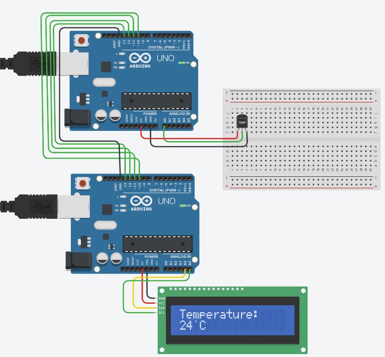
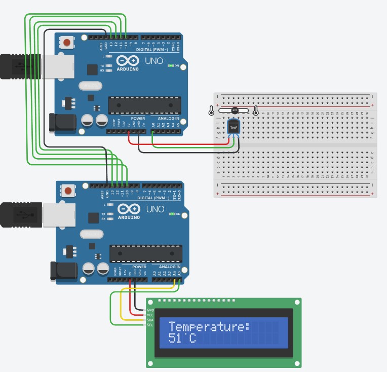
}Results
The results demonstrate the condition of the temperature transmitted from the slave to the master. The data goes from the upper Arduino to the lower (master) through the SPI communication. The results display 24 and 51 degrees Celsius temperatures on the LCD of the master Arduino.
What’s Next
Please find more tutorials on Arduino in peppe8o Arduino archives.
Enjoy!
Umar Jamil
For any queries and help with work, please contact me at:
Whatsapp: +92-346-661-7017/ Link Fiverr for order custom work
Email: umarjamil0007@gmail.com

I'm an Electronic Engineer, well-skilled to solve the issues of hardware and software. I do have laboratory which contains unlimited sensors and modules for testing the working. Also, I am experienced in Arduino programming, Android mobile application, microcontroller programming, IOTs and embedded projects. I provide services to control, realize the sensor data in the Mobile Application. For any queries and help for work Contact: Whatsapp:+92-346-661-7017 Email: umarjamil0007@gmail.com
![]()


