In my projects with Raspberry PI I always has been fashinated by the infinite fields of application for this fantastic board. One of my preferred is robotics, and this requires the control of arms, wheels and gears by using motors.
Stepper motors are the most common motor type in commerce for these projects, because of their precision.
In this article I’ll show you you to control a simple stepper motor with a Raspberry Pi Zero W.
As usual, I suggest adding from now to your favourite e-commerce shopping cart all the needed hardware, so that at the end you will be able to evaluate overall costs and decide if to continue with the project or remove them from the shopping cart. So, hardware will be only:
Apart from Raspberry PI and SD card, you can also find stepper motor, motor driver and wiring inside the cheap and complete Elegoo kit I reviewed in Elegoo kit review post.
Check hardware prices with following links:
Before starting, let me expose some considerations on hardware.
Raspberry Pi Zero W kit comes with a GPIO header not connected to the board (why? I really don’t know…). So you have 2 options:
About the choice of Elegoo parts, I choose them because they are cheap and enoght for my very first experiment. I must state that these motors are a little slow for robotics projects, but they appears to be precise. They come in a kit including also some female-male dupont cables, but if you don’t have a breadboard you will need to buy one or to buy other female-female dupont cables.
Regarding the power supply, it is possible to power the motor directly from RPI GPIOs (there are some pins cabled to ground and some other cabled to 5V). The second option is to use an external power supply which can erogate 5V. The second option is mine one. Built this with an old electrical screwdriver, detaching the battery box and identifying positive and negative connectors. I used also 4x rechargable AA battery providing 1,2V each one and connected it with 2 male-female dupont cables (from male side):
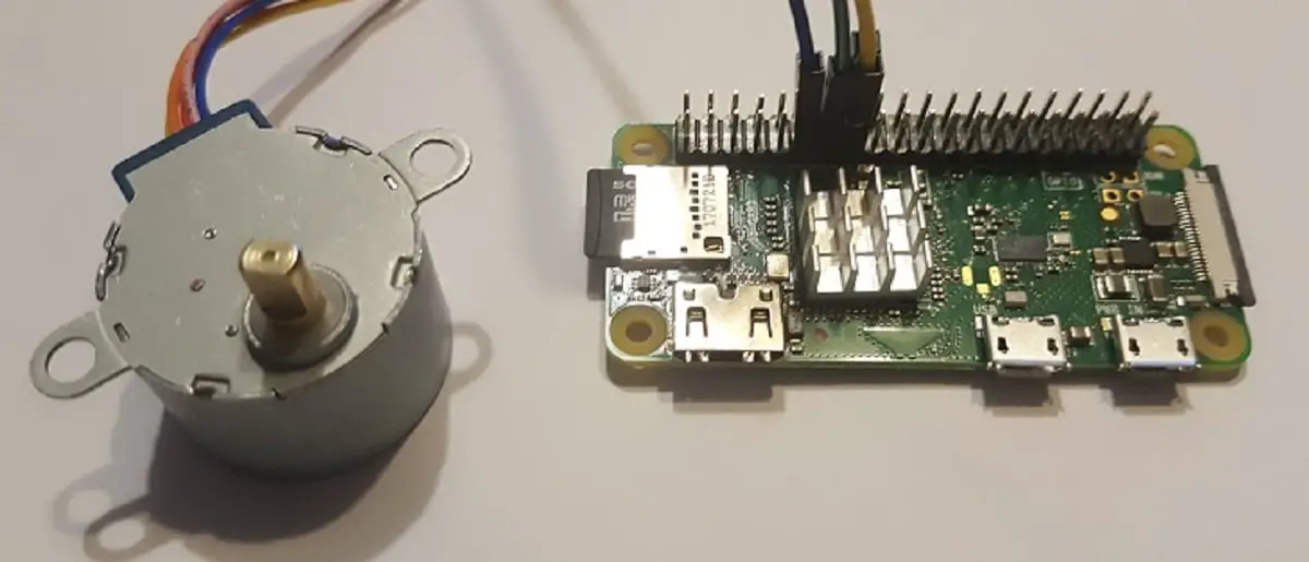
The following picture shows how connections have been cabled in my lab:
The stepper motor comes with a pre-installed connector that you can directly connect to ULN2003 controller. All other connection are made with dupont cables.
To identify GPIO in Raspberry Pi Zero, refer to the following picture:
This numbers both GPIO IDs and phisical positions. Using RPI.GPIO python libary requires the use of GPIO ID instead of phisical position. The picture above shows also pins usable to supply power (5V and 3V3) and ground.
We use:
so having the following:
If you want to power the motor with RPI power PINs, you will connect one of Ground pins to ULN2003 negative pin and one of 5V pins to ULN2003 positive pin.
In the following picture, the ULN2003 wiring:
…and the overall picture:
We’ll start from a clean Raspberry PI OS Lite installation. Once connected via ssh to your RPI, update first of all:
sudo apt update -y && sudo apt upgrade -yRPI.GPIO should be already installed (otherwise, you can get it installed with the command “sudo apt install python3-rpi.gpio”).
Now we need a Python script to control the stepper motor with our Raspberry Pi. For this purpose, I prepared a simple python script. You can just download it and align the script to your wiring configuration:
So, firstly get the script in your RPI:
wget https://peppe8o.com/download/python/steppermotor/stepper.pyThis script is based on producer step sequence schema:
| SEQ1 | SEQ2 | SEQ3 | SEQ4 | SEQ5 | SEQ6 | SEQ7 | SEQ8 | |
| IN4 | 1 | 1 | 0 | 0 | 0 | 0 | 0 | 1 |
| IN3 | 0 | 1 | 1 | 1 | 0 | 0 | 0 | 0 |
| IN2 | 0 | 0 | 0 | 1 | 1 | 1 | 0 | 0 |
| IN1 | 0 | 0 | 0 | 0 | 0 | 1 | 1 | 1 |
Each sequence step (from 1 to 8) is a GPIOs status to set from RPI to ULN2003.
You can imagine this table as a composition of 8 arrays (each one with 4 digits). This can be also seen as an ordered composition of 2 kinds of arrays (0,0,0,1 and 0,0,1,1) alternated and rotating by one digit. In python, array rotation can be implemented with the simple line:
rotated_array = array[n:]+arr[:n]
where “n” is the number of rotation steps. To rotate by 1 step, this string becomes :
rotated_array = array[1:]+arr[:1]
Because arrays are composed by 4 digit, opposite rotation can be achieved with a 3 step rotation:
rotated_array = array[3:]+arr[:3]
If you need to align code to your cutomized wiring or if you need to change the stepper motor delay, edit it with the following terminal command:
nano stepper.pyIf your cabling is different from mine, identify the row where chan_list is defined. The original one appears as the following (including comments):
chan_list = [17,27,22,23] # GPIO ports to useYou can also edit delay var from current “.001” value to higher one. The higher the value the lower the rotation.
delay=.01 # delay between each sequence stepSave and close the file (CTRL+X).
Now you can easily test your lab by launching a simple command:
python3 stepper.pyand you should see the motor rotating.
For opposite rotation, as previously described edit:
arrOUT = arr1[1:]+arr1[:1]to:
arrOUT = arr1[3:]+arr1[:3] Interested in more RPI projects? Take a look at peppe8o Raspberry PI tutorials.
Enjoy!
In this tutorial, we will use two Arduino Uno to demonstrate the Serial Peripheral Interface…
In this tutorial, we will be making an automatic irrigation system (AIS) with Arduino and…
This tutorial will show you how to use Python Virtual Environment with Raspberry PI computer…
This tutorial will show you how to get betting odds with Raspberry PI by using…
This tutorial will show you how to perform the backup of Raspberry PI (computer board)…
This tutorial will show you how to install Honeygain on a Raspberry PI computer board…


