Active buzzer is a cheap electronic component able to produce a sound when powered with a DC current.
Differently from passive buzzer, this element includes a built-in oscillator. This allow user to make it working by powering on and without the need to simulate an electronic square wave. It includes 2 rear pins. The longer one is positive and must be connected to power signal. The shorter one is ground and must be connected to 0V (ground).
Final result is a semplified programming script to use it.
In this guide I’ll show you how to use an activebuzzer with your Raspberry PI. I will use a Raspberry PI Zero W, but this guide will work also with newer Raspberry PI boards.
As usual, I suggest adding from now to your favourite e-commerce shopping cart all the needed hardware, so that at the end you will be able to evaluate overall costs and decide if to continue with the project or remove them from the shopping cart. So, hardware will be only:
Rearding active buzzer, you can also evaluate the cheap Elegoo starter kit, which includes a number of sensors useful for your electronics projects.
Check hardware prices with following links:
Following picture shows wiring diagram adopted:
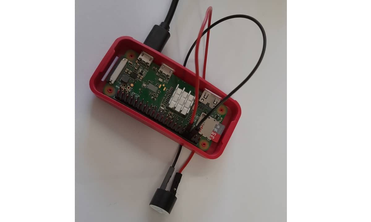
Following picture shows overall project:
An headless installation will be performed. However, also a Desktop installation works, using terminal.
This procedure starts from operating system setup installing Raspberry PI OS Lite.
Align your Raspberry PI to the latest updates. From terminal:
sudo apt update
sudo apt upgrade
RPI.GPIO should be already installed (otherwise, you can get it installed with the command “sudo apt install python3-rpi.gpio”).
Python script becomes really simple with GPIO. You can download it in your Raspberry PI from terminal:
wget https://peppe8o.com/download/python/active_buzzer.pyBelow the script description.
Before all, needed libraries are imported:
import sys
import RPi.GPIO as GPIO
import time
Signal PIN (pin where the positive cable is connected) is defined in a variable for better management. Be aware to use GPIO BCM naming. In my cabling, it is number 14. It is also set to be an output pin:
signalPIN = 14
GPIO.setmode(GPIO.BCM)
GPIO.setup(signalPIN,GPIO.OUT)
At this point, our buzzer is ready to work. Our script will set its power output on and wait 5 seconds: this means that buzzer will produce its sound for 5 seconds. Then GPIO PINs are cleaned and script exits:
GPIO.output(signalPIN,1)
time.sleep(5)

GPIO.cleanup()
sys.exit()
Enjoy!
In this tutorial, we will use two Arduino Uno to demonstrate the Serial Peripheral Interface…
In this tutorial, we will be making an automatic irrigation system (AIS) with Arduino and…
This tutorial will show you how to use Python Virtual Environment with Raspberry PI computer…
This tutorial will show you how to get betting odds with Raspberry PI by using…
This tutorial will show you how to perform the backup of Raspberry PI (computer board)…
This tutorial will show you how to install Honeygain on a Raspberry PI computer board…


