Last Updated on 26th January 2022 by peppe8o
In this tutorial, I’m going to show how to install Arduino IDE in a Windows PC (in my case Windows 10, but should be the same also for previous Windows versions). After installed, We’ll connect IDE to Arduino with its USB cable and test our first Arduino sketch.
A sketch is how Arduino programs are named. It’s a piece of code uploaded to an Arduino board. Once uploaded, Arduino will run this code until a new code is uploaded. So, also if you remove the power cable and plug in it again, Arduino will restart again executing the last sketch uploaded.
If you want to know the differences between Arduino and Raspberry PI (the 2 most famous small board), please refer to Arduino vs Raspberry PI article.
What We Need
As usual, I suggest adding from now to your favourite e-commerce shopping cart all the needed hardware, so that at the end you will be able to evaluate overall costs and decide if to continue with the project or remove them from the shopping cart. So, hardware will be only:
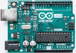
- Arduino Board with its USB cable (or you can also buy an Elegoo Arduino compatible kit, which has complete compatibility with Arduino projects)
- Windows PC with at least 700MB of disk space and administrative rights
Install IDE in Your Windows PC
Download Arduino IDE for Windows from Arduino Software Download page (Windows installer, about 120MB). For installation, it will require about 600MB of disk space.
Install the exe like all other Windows programs (you will need administrative permissions): double click on the downloaded exe file. Setup will start with License Agreement confirmation:

After confirming with “I Agree” button, you will be asked to select components to install:

I will click next to install all components. Now we have to set select where to install Arduino:
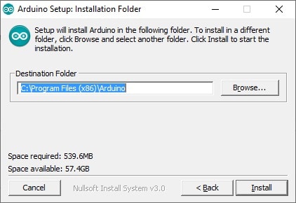
select path or use the default one (suggested) and press “Install” button.
The installation will require about a minute (depending on PC hardware) and should end with a “Completed” window if all have gone right:
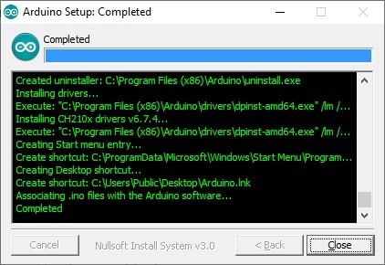

Click Close to end IDE installation step. You should now have a new Icon on your desktop (like the one at the right of this text). You can also find the Arduino link in your Programs.
Now lauch Arduino IDE. At first execution, a Windows Firewall warning can pop up. In this case, you need to grant access to be able to download and install Drivers or libraries downloaded from the internet.
Once started, the default screen will appear:
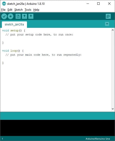
Please note the 5 buttons under the menu bar on top. From left to right:
- Verify > compile current code and check if it is correct
- Upload > compile current code and send it to Arduino
- New > open a new IDE window
- Open > allow user to select and open a saved sketch
- Save > save current sketch
Connect IDE To Arduino
It’s time to connect the Arduino board. Plug USB cable between Arduino and your PC. No power supply is needed, Arduino will be powered from the USB port. Once powered, you will see 2 LEDs on: the green Power LED and an amber LED blinking.
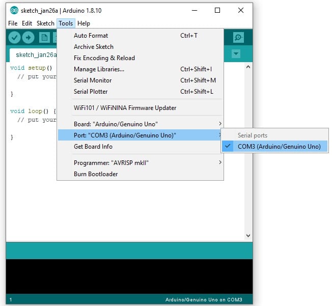
From IDE, go to Tools -> Port -> select the option referring to Arduino inside
round brackets. In my case, my PC port corresponds to COM3, but the number can change based on which USB port you use in your PC:
Test Connection
We’ll test our Arduino with a very simple example: the blink sketch. This sketch drives the little amber built-in LED on the Arduino board. You can certainly note that once powered, the amber LED is already blinking. Yes, it’s true and happens because usually Arduino boards are generally shipped with Blink sketch pre-installed. So, our test will be to change blinking frequency.
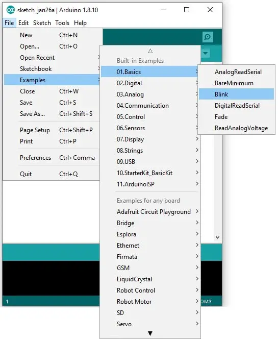
In Arduino IDE, go to File > Examples > 01.Basics and click Blink:
A new IDE session will start, with the following code (excluding initial comments, which are greyed):
// the setup function runs once when you press reset or power the board
 void setup() {
   // initialize digital pin LED_BUILTIN as an output.
   pinMode(LED_BUILTIN, OUTPUT);
 }
 // the loop function runs over and over again forever
 void loop() {
   digitalWrite(LED_BUILTIN, HIGH);   // turn the LED on (HIGH is the voltage level)
   delay(1000);                       // wait for a second
   digitalWrite(LED_BUILTIN, LOW);    // turn the LED off by making the voltage LOW
   delay(1000);                       // wait for a second
 }
This very simple sketch is divided into 2 main parts:
- setup section – which initialize main functions and variables
- loop section – which excecutes commands in an infinite cycle from first loop line to last one, then restarting from loop start
Inside loop, we can find the two commands to set LED on / off (“HIGH” / “LOW”) and delay commands which controls how long each state lasts. So, by modifying the delay value we can control the blinking to make it more or less frequent.
Edit the first delay to 100 and the second one to 3000, as follows:
void loop() {
   digitalWrite(LED_BUILTIN, HIGH);   // turn the LED on (HIGH is the voltage level)
   delay(100);                       // wait for a second
   digitalWrite(LED_BUILTIN, LOW);    // turn the LED off by making the voltage LOW
   delay(3000);                       // wait for a second
 }
Click on the Upload button. You should see Arduino reconfiguring itself and then amber LED blinking with different frequencies.
Your first Arduino sketch is running!
Enjoy!
Open source and Raspberry PI lover, writes tutorials for beginners since 2019. He's an ICT expert, with a strong experience in supporting medium to big companies and public administrations to manage their ICT infrastructures. He's supporting the Italian public administration in digital transformation projects.

