
Last Updated on 20th July 2026 by peppe8o
Infrared sensors are really common to devices which need to be controlled from a remote within reduced distances. Typical applications are in remoting TV, media center, robots, air conditioning systems, etc.
With the growth of mass production, their prices have plummeted and can be found on e-commerce websites.
Linux systems have a spread package called LIRC (Linux Infrared Remote Control). This is a really handy package with most common remotes, but it becomes a little tricky when you havea remote not included in LIRC remotes database because you have to know you remote infrared signal map to create your custom configuration file.
A second chance comes from ir-keytable package. This package is really simple to use and allows you to record one by one you remote keys signals and map them to your custom config file, even without knowing signal profile of your remote.
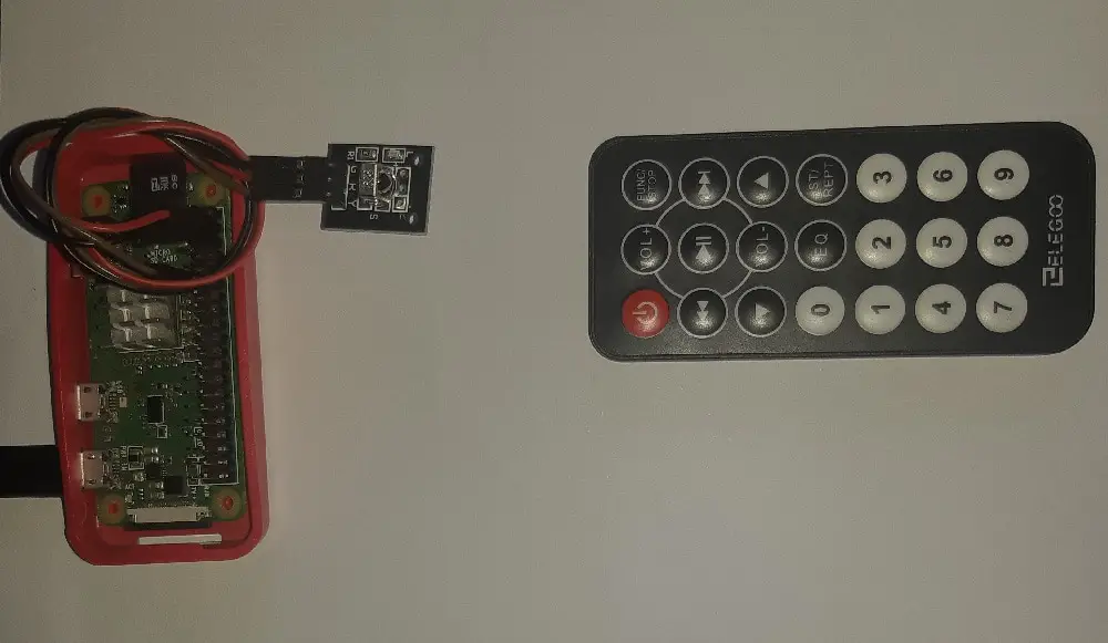
In this article, I’ll show how to connect your Raspberry PI to an IR receiver and control it from a remote with ir-keytable. For this article, I’m going to use a Raspberry PI Zero W, but the same procedure works also with newer Raspberry PI boards.
How Infrared Sensors Work
Before starting with terminal commands, let’s dig on how they works. A very good explaination is available at Adafruit Infrared Sensor description page:
IR detectors are little microchips with a photocell that are tuned to listen to infrared light. They are almost always used for remote control detection – every TV and DVD player has one of these in the front to listen for the IR signal from the clicker. Inside the remote control is a matching IR LED, which emits IR pulses to tell the TV to turn on, off or change channels. IR light is not visible to the human eye, which means it takes a little more work to test a setup.
There are a few difference between these and say a CdS Photocells:– IR detectors are specially filtered for Infrared light, they are not good at detecting visible light. On the other hand, photocells are good at detecting yellow/green visible light, not good at IR light
– IR detectors have a demodulator inside that looks for modulated IR at 38 KHz. Just shining an IR LED wont be detected, it has to be PWM blinking at 38KHz. Photocells do not have any sort of demodulator and can detect any frequency (including DC) within the response speed of the photocell (which is about 1KHz)
– IR detectors are digital out – either they detect 38KHz IR signal and output low (0V) or they do not detect any and output high (5V). Photocells act like resistors, the resistance changes depending on how much light they are exposed to.
What We Need
As usual, I suggest adding from now to your favourite e-commerce shopping cart all the needed hardware, so that at the end you will be able to evaluate overall costs and decide if to continue with the project or remove them from the shopping cart. So, hardware will be only:
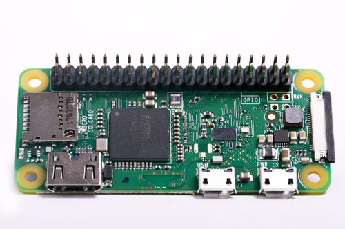
- Raspberry PI Zero W (including proper power supply or using a smartphone micro usb charger with at least 3A) or newer Raspberry PI Board
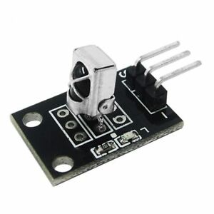
- Infrared Sensor
- IR Remote
- dupont wiring (female to female)
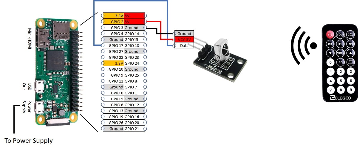
Wiring Diagram
The following picture shows the wiring diagram adopted:
Step-by-Step Procedure
Prepare OS
Install OS following install Raspberry PI OS Lite guide. Make your OS up to date:
sudo apt update
sudo apt upgrade
Prepare ir-Keytable
Add GPIO to Device Tree overlay in boot config. Edit /boot/config.txt
sudo nano /boot/config.txtUncomment and change dtoverlay row as following (GPIO pin parameter refers to BCM naming for RPI pins):
dtoverlay=gpio-ir,gpio_pin=17Close and save. Reboot your Raspberry PI:
sudo rebootAfter restart, please login again from terminal and install ir-keytable package:
sudo apt install ir-keytableMap Your Remote With ir-Keytable
Before starting to customize our remote mapping, we can try our luck to find supported remotes. To list supported pre-built Keymaps:
ls /lib/udev/rc_keymaps/ir-keytable has less pre-built remotes than LIRC, but I prefer it because – as said – it is simpler to customize. If you was lucky and found your remote in pre-built ones, than you can simply test it by typing “ir-keytable -t” on terminal and testing if buttons work. If it returns key names, then you are ok and this procedure ended.
Create Your Custom Mapping
For not so lucky people, list supported kernel protocols with ir-keytable command:
pi@raspberrypi:~ $ sudo ir-keytable
Found /sys/class/rc/rc0/ (/dev/input/event0) with:
Name: gpio_ir_recv
Driver: gpio_ir_recv, table: rc-rc6-mce
LIRC device: /dev/lirc0
Attached BPF protocols: Operation not permitted
Supported kernel protocols: lirc rc-5 rc-5-sz jvc sony nec sanyo mce_kbd rc-6 sharp xmp imon
Enabled kernel protocols: lirc rc-6
bus: 25, vendor/product: 0001:0001, version: 0x0100
Repeat delay = 500 ms, repeat period = 125 ms
In next step we’ll use ir-keytable in test mode to identify and take note about supported protocol and keys pressure ID. Let’s start test procedure with all protocols supported:
sudo ir-keytable -v -t -p rc-5,rc-5-sz,jvc,sony,nec,sanyo,mce_kbd,rc-6,sharp,xmpThe initialization procedure will start:
Found device /sys/class/rc/rc0/
Parsing uevent /sys/class/rc/rc0/lirc0/uevent
/sys/class/rc/rc0/lirc0/uevent uevent MAJOR=252
/sys/class/rc/rc0/lirc0/uevent uevent MINOR=0
/sys/class/rc/rc0/lirc0/uevent uevent DEVNAME=lirc0
Input sysfs node is /sys/class/rc/rc0/input0/
Event sysfs node is /sys/class/rc/rc0/input0/event0/
Parsing uevent /sys/class/rc/rc0/input0/event0/uevent
/sys/class/rc/rc0/input0/event0/uevent uevent MAJOR=13
/sys/class/rc/rc0/input0/event0/uevent uevent MINOR=64
/sys/class/rc/rc0/input0/event0/uevent uevent DEVNAME=input/event0
Parsing uevent /sys/class/rc/rc0/uevent
/sys/class/rc/rc0/uevent uevent NAME=rc-rc6-mce
/sys/class/rc/rc0/uevent uevent DRV_NAME=gpio_ir_recv
/sys/class/rc/rc0/uevent uevent DEV_NAME=gpio_ir_recv
input device is /dev/input/event0
/sys/class/rc/rc0/protocols protocol rc-5 (enabled)
/sys/class/rc/rc0/protocols protocol nec (enabled)
/sys/class/rc/rc0/protocols protocol rc-6 (enabled)
/sys/class/rc/rc0/protocols protocol jvc (enabled)
/sys/class/rc/rc0/protocols protocol sony (enabled)
/sys/class/rc/rc0/protocols protocol rc-5-sz (enabled)
/sys/class/rc/rc0/protocols protocol sanyo (enabled)
/sys/class/rc/rc0/protocols protocol sharp (enabled)
/sys/class/rc/rc0/protocols protocol mce_kbd (enabled)
/sys/class/rc/rc0/protocols protocol xmp (enabled)
/sys/class/rc/rc0/protocols protocol imon (disabled)
/sys/class/rc/rc0/protocols protocol lirc (enabled)
Opening /dev/input/event0
Input Protocol version: 0x00010001
Protocols changed to rc-5 rc-5-sz jvc sony nec sanyo mce_kbd rc-6 sharp xmp
Testing events. Please, press CTRL-C to abort.
you are now prompted to generate key pressure events. Point your remote to IR sensor and press a key. In my test, with an Elegoo remote, the following rows are generated:
1274.230088: lirc protocol(nec): scancode = 0x45
1274.230144: event type EV_MSC(0x04): scancode = 0x45
1274.230144: event type EV_SYN(0x00).
The first line shows that my remote uses “nec” protocol. trace this in your notes. Protocol will be the same for all buttons.
The first and second rows show that my key pressure generated a “0x45” scancode. I had this event by pressing my Power button on remote. So my first matching is:
0x45 = Power key
Repeat this step for each remote button and create a mapping table similar to the following one:
protocol: nec

0x45 = Power
0x46 = Vol+
0x47 = FUNC/STOP
0x44 = BCW
0x40 = PLAY/PAUSE
0x43 = FRW
0x07 = DOWN
0x15 = VOL-
0x09 = UP
0x16 = 0
0x19 = EQ
0x0d = ST/REPT
0x0c = 1
0x18 = 2
0x5e = 3
0x08 = 4
0x1c = 5
0x5a = 6
0x42 = 7
0x52 = 8
0x4a = 9
Create Your Custom .toml File From Mapping
In this section, we are going to create our custom .toml file that will be used by ir-keytable at kernel level. A .toml file is a simple file with a short description of remote name and a map of system buttons to scancodes. Usable system buttons are listed in following text file you can get from my dowload area:
ir-keytable available keycodes.txt
Usually, the correct ones are these keys starting with “KEY_” prefix.
Create a toml file similar to (or download from the next link) my Elegoo.toml, but with your data you noted in the previous step and related kernel keys:
[[protocols]]
name = "Elegoo"
protocol = "nec"
variant = "nec32"

[protocols.scancodes]
0x45 = "KEY_POWER"
0x46 = "KEY_VOLUMEUP"
0x47 = "KEY_FN_S"
0x44 = "KEY_BACK"
0x40 = "KEY_PLAYPAUSE"
0x43 = "KEY_FORWARD"
0x07 = "KEY_DOWN"
0x15 = "KEY_VOLUMEDOWN"
0x09 = "KEY_UP"
0x16 = "KEY_0"
0x19 = "KEY_EQUAL"
0x0d = "KEY_REPLY"
0x0c = "KEY_1"
0x18 = "KEY_2"
0x5e = "KEY_3"
0x08 = "KEY_4"
0x1c = "KEY_5"
0x5a = "KEY_6"
0x42 = "KEY_7"
0x52 = "KEY_8"
0x4a = "KEY_9"
To test our toml file, we need to clean current keytable, load toml file, read i to check and then we can test (diring test, consider that if you press power button and if it works, then your Raspberry PI will shut down):
sudo ir-keytable -c
sudo ir-keytable -w /pathToFile/your.toml
sudo ir-keytable -r
sudo ir-keytable -t
Please find below my terminal output for comparison:
pi@raspberrypi:~ $ sudo ir-keytable -c
Old keytable cleared

pi@raspberrypi:~ $ sudo ir-keytable -w Elegoo.toml
Wrote 21 keycode(s) to driver
Protocols changed to nec

pi@raspberrypi:~ $ sudo ir-keytable -r
scancode 0x0007 = KEY_DOWN (0x6c)
scancode 0x0008 = KEY_4 (0x05)
scancode 0x0009 = KEY_UP (0x67)
scancode 0x000c = KEY_1 (0x02)
scancode 0x000d = KEY_REPLY (0xe8)
scancode 0x0015 = KEY_VOLUMEDOWN (0x72)
scancode 0x0016 = KEY_0 (0x0b)
scancode 0x0018 = KEY_2 (0x03)
scancode 0x0019 = KEY_EQUAL (0x0d)
scancode 0x001c = KEY_5 (0x06)
scancode 0x0040 = KEY_PLAYPAUSE (0xa4)
scancode 0x0042 = KEY_7 (0x08)
scancode 0x0043 = KEY_FORWARD (0x9f)
scancode 0x0044 = KEY_BACK (0x9e)
scancode 0x0045 = KEY_POWER (0x74)
scancode 0x0046 = KEY_VOLUMEUP (0x73)
scancode 0x0047 = KEY_FN_S (0x1e3)
scancode 0x004a = KEY_9 (0x0a)
scancode 0x0052 = KEY_8 (0x09)
scancode 0x005a = KEY_6 (0x07)
scancode 0x005e = KEY_3 (0x04)
Enabled kernel protocols: lirc nec

pi@raspberrypi:~ $ sudo ir-keytable -t
Testing events. Please, press CTRL-C to abort.
749.430103: lirc protocol(nec): scancode = 0x18
749.430181: event type EV_MSC(0x04): scancode = 0x18
749.430181: event type EV_KEY(0x01) key_down: KEY_2(0x0003)
749.430181: event type EV_SYN(0x00).
749.480258: lirc protocol(nec): scancode = 0x18 repeat
749.480310: event type EV_MSC(0x04): scancode = 0x18
749.480310: event type EV_SYN(0x00).
749.610091: event type EV_KEY(0x01) key_up: KEY_2(0x0003)
749.610091: event type EV_SYN(0x00).
750.430096: lirc protocol(nec): scancode = 0x19
750.430167: event type EV_MSC(0x04): scancode = 0x19
750.430167: event type EV_KEY(0x01) key_down: KEY_EQUAL(0x000d)
750.430167: event type EV_SYN(0x00).
750.560106: event type EV_KEY(0x01) key_up: KEY_EQUAL(0x000d)
750.560106: event type EV_SYN(0x00).
751.710097: lirc protocol(nec): scancode = 0xd
751.710168: event type EV_MSC(0x04): scancode = 0x0d
751.710168: event type EV_KEY(0x01) key_down: KEY_REPLY(0x00e8)
751.710168: event type EV_SYN(0x00).
751.770263: lirc protocol(nec): scancode = 0xd repeat
751.770319: event type EV_MSC(0x04): scancode = 0x0d
751.770319: event type EV_SYN(0x00).
751.900086: event type EV_KEY(0x01) key_up: KEY_REPLY(0x00e8)
751.900086: event type EV_SYN(0x00).
If you have a similar behaviour and keys showed are the same you pressed, then your toml file is valid and working.
Make Your Mapping Permanent
We need now to make our configuration permanent after reboot.
Move your toml file to “/etc/rc_keymaps/”
sudo mv /pathToFile/your.toml /etc/rc_keymaps/Edit /etc/rc_maps.cfg to add a row
sudo nano /etc/rc_maps.cfgAdd a row on the devices table referencing your toml file. Use * wildcard both on the driver and table columns. In my case, my file is named Elegoo.toml and my rc_maps.cfg section will appear as the following:
.....
.....
# Table to automatically load the rc maps for the bundled IR's provided with the
# devices supported by the linux kernel
# driver table file
*    *                      Elegoo.toml
*    rc-adstech-dvb-t-pci   adstech_dvb_t_pci.toml
*    rc-alink-dtu-m         alink_dtu_m.toml
*    rc-anysee              anysee.toml
.....
.....
Test configuration loading:
sudo ir-keytable -a /etc/rc_maps.cfg -s rc0This should return something like the following (keycodes number and protocol may vary according to your toml:
Old keytable cleared
Wrote 21 keycode(s) to driver
Protocols changed to nec
Moreover, “ir-keytable -r” terminal command should show your mapping.
To make it permanent after reboot, edit /etc/rc.local
sudo nano /etc/rc.localand add loading configuration command before “exit 0” final row:
.....
.....
  printf "My IP address is %s\n" "$_IP"
fi

ir-keytable -a /etc/rc_maps.cfg -s rc0

exit 0
Reboot and check if it is persistent.
Enjoy!

Open source and Raspberry PI lover, writes tutorials for beginners since 2019. He's an ICT expert, with a strong experience in supporting medium to big companies and public administrations to manage their ICT infrastructures. He's supporting the Italian public administration in digital transformation projects.
![]()
![]()
![]()
![]()
![]()
![]()
![]()


thank you for your very usefull article.
I had my IR-receiver installed in no time and it works.
Great.
The only thing after a reboot, it did not work anymore.
I had to put sudo in front of the line in rc.local file:
sudo ir-keytable -a /etc/rc_maps.cfg -s rc0
After that it worked after a reboot as well.
Really strange: rc.local should run as root… however happy that it worked also for you!
hy peppe80
I removed the sudo in the rc.local file as you stated that it runs as root.
Then I performed a reboot and bingo, it did work.
Just to be sure, I powered off, powered up, and it still works.
So why it did not after the very first try, I don’t know. The rc.local file is like you posted.
Thanks again.
This is THE BEST tutorial for enabling your Raspberry Pi to see IR input…. I’ve worked thru quite a few!
Thank you!
Thank you, Mike. Glad this helped you too.
Yes, thank you again!
Over the past two days, I’ve mapped keys on my remote and made some keybindings (using a method I found elsewhere) to make buttons initiate a shutdown or reboot of the host Raspberry Pi. Next, I’m going to use the IR remote to control a string of RGB LEDs…. seems like a good match. I’m thinking the approach should be based on a python script that watches for inputs and gives outputs.
Have you done anything like this in your tutorials or playing around with the Pi…?
This is a very good idea. This shouln’t be too complicated from theorical perspective as with python subprocess library you can execute shell commands. But requires time, as you should manage a command running in background (ir-keytable when collecting test data) and at same time ask user what key he pressed to save matching. But the most time with programs is managing exceptions, differences between a huge IR hardware world and so on. Writing new programs is a quite simple job, but the hard part is managing them
I would have loved to meet this guide 6 hours ago….. just golden. Funny enough I have the same remote control. super eaaaasy.
Thank you for your feedback, Carlo
I just wanted to say Thanks! I’ve been struggling with my IR receiver and my Buster raspberryOS install for weeks. I’ve read countless tutorials with different ways to get my various IR remotes to work with my RaspberryPi and none of them completely worked. Your information here worked 1st try. I am running a headless Pi and am going to use an old IR remote to control my Mopidy install.
Glad it helped you too. If you want to give back, share this post with your friends 😉
This is incredible. Got my Elegoo working quickly and learned a lot about keycodes and persistent changes.
Learned more from 20 minutes of this article than 20 hours of the Arch Wiki
Thank you for your feedback, Jonathan. I’m very happy when my tutorials help people in learning. I hope you will enjoy also the other articles available in my blog
Hi Peppe, thanks for the wonderful guide!! I just have a problem with sending commands can you help me? How do I send stored commands using an IR-TX connected to the Raspberry?
Thank you!!
Hi Dante,
Thank you for your appreciation. This tutorial is about an RX sensor and the remote sends IR commands. To solve your issue we need to know the model of your TX/RX sensor and Search for tutorials about that
So this in the link is the IR transmitter. What I would like to do is control a hifi device via raspberry. I have already taken the commands from the LIRC database, only that once the configuration is done, when I go to send the command the presence LED on the TX card lights up but nothing happens on the device. Is there any recent guide for configuring LIRC as a transmitter? because the ones I found are all dated. Thank you in advance for your availability
https://www.ebay.it/itm/284116631419?mkcid=16&mkevt=1&mkrid=711-127632-2357-0&ssspo=-KjvLcpwRNS&sssrc=2047675&ssuid=2UkpvlBvSRq&var=585607060562&widget_ver=artemis&media=COPY
I got a tx card on ebay. What I need to do is control a hi-fi device via infrared by sending commands from the raspberry. I tried using Lirc but the guides are a bit dated and when I go to send the irsend command the status LED on the tx board flashes but does not transmit anything. Can you help me ? Thank you in advance 😊
Hello,
Thank you for this tutorial!
I have manged to complete your tutorial for my remote and I get correct mapping of scan keys to the scan codes.
For my remote that uses nec protocol, scan codes 0x16, 0x19 and 0x47 are mapped to KEY_VOLUMEDOWN, KEY_VOLUMEUP, and KEY_MUTE.
I expected that I can reboot my RPi (4b or zero 2w) and expect the IR remote to control volume and mute? It’s not doing it. The RPi is headless and running Bookworm x64 Lite.
Could you kindly let me know if I need to do anything more? I am not a coder and so need some hand-holding, please. I will provide additional information as needed.
Thank-you!
Hi Ravindra. Please let me understand better the problem. After you reboot the raspberry PI, the keys doesn’t work? (sorry for the late reply)
Hi
How can I use the remote codes of my remote controller in Python?
Thanks
Hi Paulo,
Python allows you to execute and read any bash command output with the
subprocesslibrary. You can use it to read the ir-keytable outputsThanks
You’re welcome! 😉
Thanks for the fantastic guide !
I do have one question though.. Is it fine to connect the IR signal out directly to the raspberry pi GPIO pins ?
I know the GPIO pins are supposed to have a max signal input voltage of 3v3, and seeing as the IR module
is being powered off 5v, would that not make the IR signal out coming from the module 5v as well ?
Regards
Nic
Hi neeek,
sorry for the late reply. Your comment is correct, you should check the output voltage from the IR receiver you use (as there are many versions on the market). If the High Voltage output is lower than 3.3V, then you can use it directly to the Raspberry PI GPIO. Otherwise you should use a voltage divider circuit (2 resistors)
Thank you so much for providing this step-by-step guide. It works perfectly.
Thank you for your feedback, Robert!
Thanks for this wonderful tutorial, everything worked beautifully. But I’m now confused as I want to trap these Key Events in a C prog and I would normally do this… if ((FileDevice = open(“/dev/input/event0”, O_RDONLY)) < 0) etc. etc. but there is no eventX for the Ir – I assume I'm looking at this in completely the wrong way – could you enlighten me.
Thanks again
Hi Mark,
I’m sorry but I can’t help you with C. With Python, I would try the evdev package to get events in my code and run whatever program I want at each trigger. I’m really sorry