
Last Updated on 30th August 2024 by peppe8o
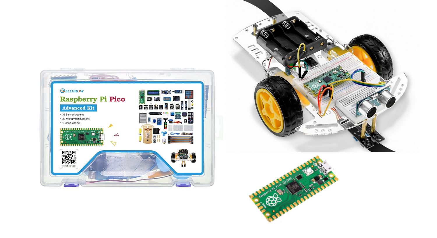
In this tutorial, I will show you my review of the Elecrow Advanced Kit for Raspberry PI Pico, a sensor, and all the parts needed to build your DIY smart car robot.
About the Kit
The kin includes all the sensors that every beginner can need for any of the most common projects. By combining them and programming the Raspberry PI Pico you can create end-less personal projects for any need. The parts list follows:
| 1x Raspberry Pi Pico with Pin headers (Optional) 2x 400 holes Solderless Breadboard 10x Colorful 5MM LEDS:1pcs each in green, red, blue, yellow and white 1x RGB module 1xButton 1x Sound Sensor 1x Mini PIR motion sensor 1x Photoresistor Module 1x Laser Transmitter 1x Passive buzzer 1x Vibration Sensor 1x Mini magnetic spring module 1x Soil moisture sensor 1x Rotary Potentiometer 1x DC motor with male Dupont Wire + fan blade x 1 1x 9G servo 1x Dual-axis XY Joystick Module 1x RC522 RFID Module 1x 4 Bits Digital LED Display Module 1x Traffic Light Display Module 1x Rotary Encoder Module 1x 1602 LCD Display Module(Blue) 1x Temperature & Humidity sensor | 1x Raindrops Module 1x Flame Sensor 1x OLED Module 1x Membrane Switch Keyboard 1x Smart car Kit 2x Crash Sensor 2x Tracking sensor 1x Ultrasonic Sensor 1x Infrared remote control 1x Infrared receiver module 1x Micro USB Cable(30cm) 1x 170 holes Solderless Breadboard 1x 65 Jumper Wire 1x 20CM Male to Female Dupont Wire 1x Clear Case 10 x 2K Ω Resistors 2x M2.5*30mm Copper Pillar 10x Phillips Pan Head Screw 10x M2.5 Nickel Hex nuts 1x 2 INCH dual-purpose screwdriver 1x Magnet(Diameter:8mm Thickness:5mm) 1x DC stepper motor driver board |
As you may notice from the list, there’s no Raspberry Pi Pico included in the package. You can buy it along with the kit, choosing if you want the Raspberry PI Pico W (with wireless, which I suggest) or the Raspberry PI Pico.
The kit also includes the case to build your DIY smart car, with all the parts and the code to get it running in your home.
The package doesn’t include a paper manual; you can download it from the Elecrow website in digital format (from the Advanced kit link in the following chapter). I think this approach is good for saving paper, reducing the environmental impact, and because the manual includes the programming code that hardly you can copy from a paper.
On the other hand, you will find the assembly sheet, showing how to put together the parts of the Smart Car.
What We Need
The kit is available from the Elecrow store and it already includes all the parts you need (besides a computer used to upload the programs to your Raspberry PI Pico). You can find it at the following link:
Elecrow Raspberry PI Pico Advanced Kit
Moreover, for the smart car kit, you will also need (not included in the kit):
- 4x AA batteries to power the Smart Car
- a soldering iron to solder motor cables
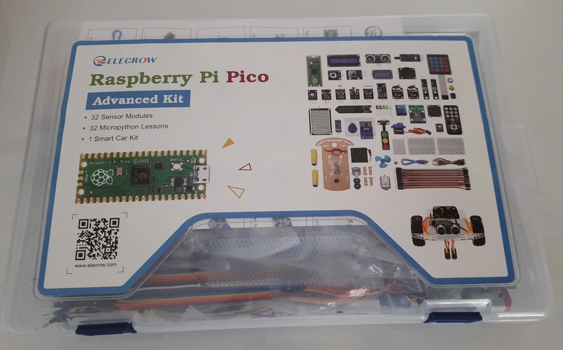
The Elecrow Advanced Kit Packaging
The kit comes in a 30cm x 20cm x 6cm plastic bag, as shown in the previous picture. The Raspberry PI Pico is delivered outside this bag, within a specific package.
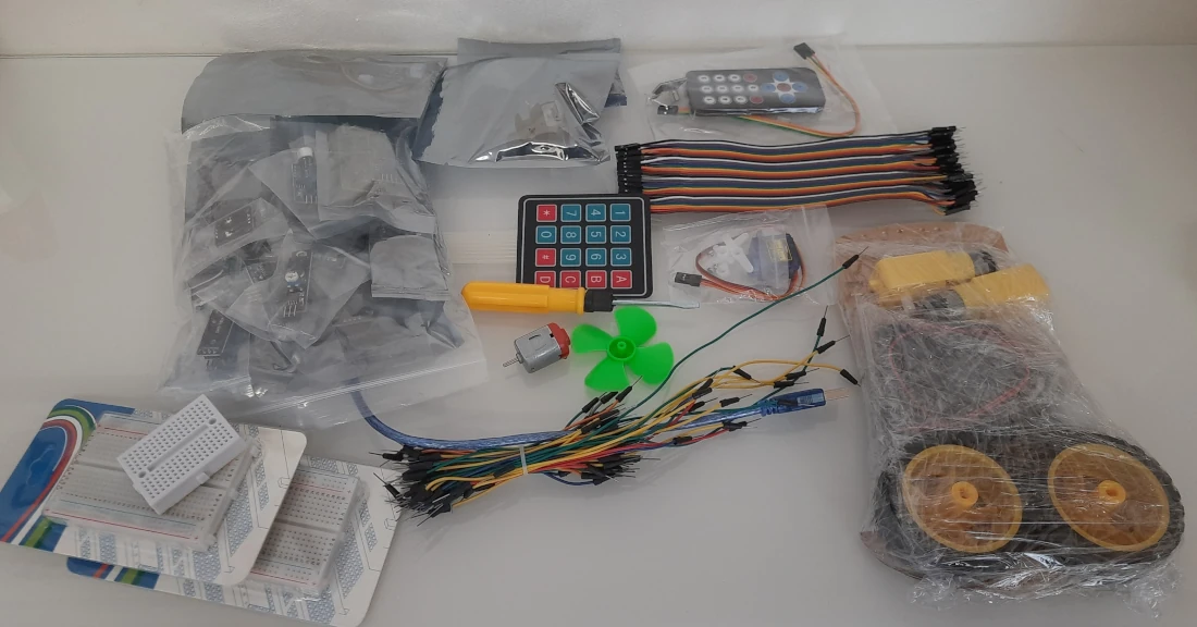
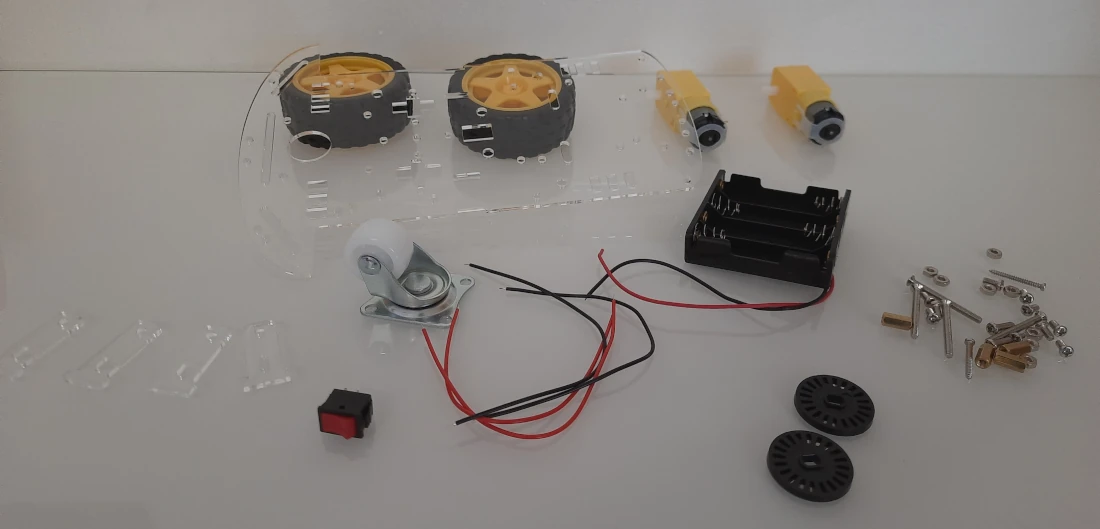
Opening the kit’s bag, you will find all the parts wrapped in smaller, plastic sachets. You will also find a screwdriver (it is always a good solution providing it with these kits), Dupont cables to connect the Raspberry PI Pico with the sensors, and 3 breadboard.
Now, let’s see at how is simple to use this kit, by assembling the Smart Car.
Assembling the Smart Car
The complete assembly instructions for the Pico Smart Car are available from the following link:
https://www.elecrow.com/download/product/RPK13250K/Map_and_Assembly_Manual.pdf
Please open the plastic enclosure keeping the smart car kit. Moreover, please remove the protective film from the surface of the acrylic parts:
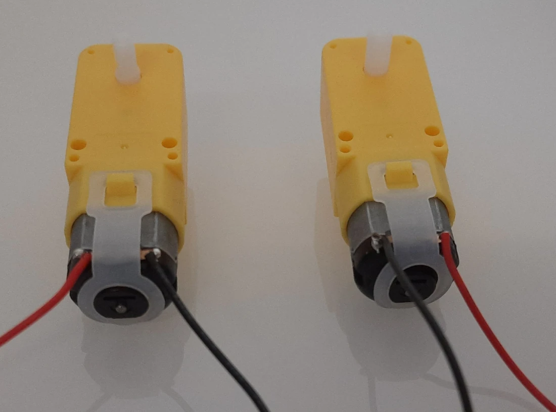
Prepare the Motors
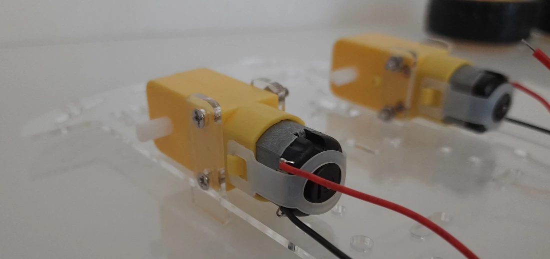
Now we must prepare the motors. In this step we must solder the cables to the motors, keeping attention to using the black wire on the left side in one motor, and the right side in the other, as shown in the following picture. This step is absolutely an adult’s job as the soldering iron gets very high temperatures and it is dangerous for kids. I also suggest removing the motors from reduction gears in order to avoid damaging them when soldering.
Assemble the Motors to the Case
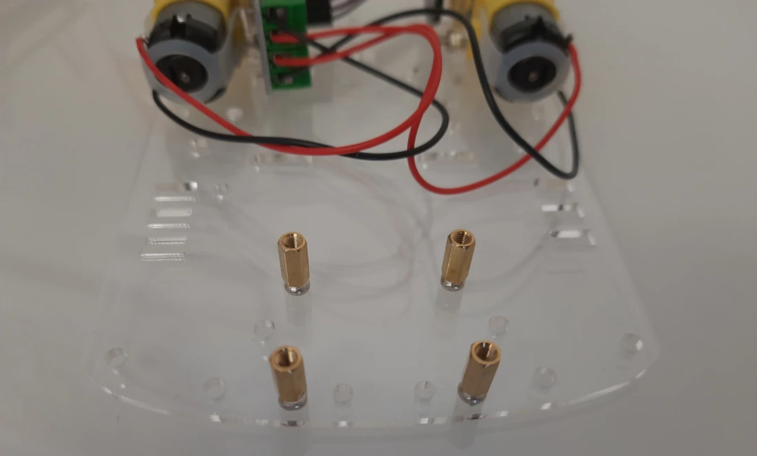
Now, please identify the holes highlighted in the following picture:
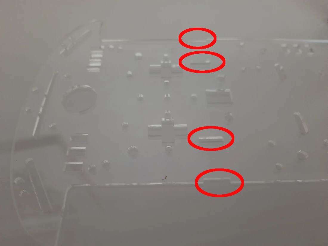
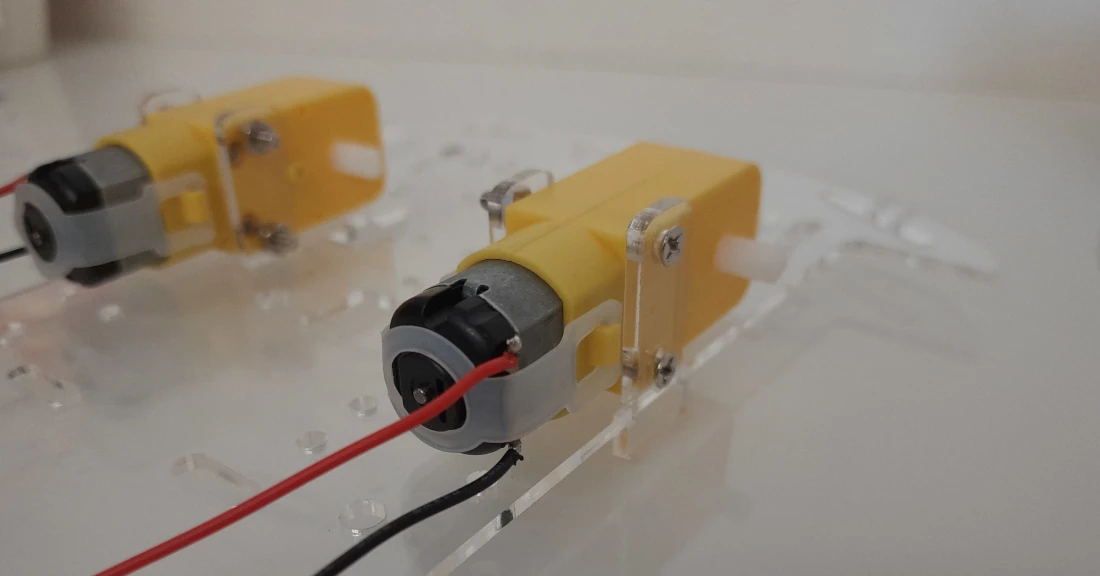
Use them to assemble the motor gears in your case, paying attention to fix them on the right side (see the picture below and use the red-black wires to correctly orientate them). For this task, please use the longer screws:
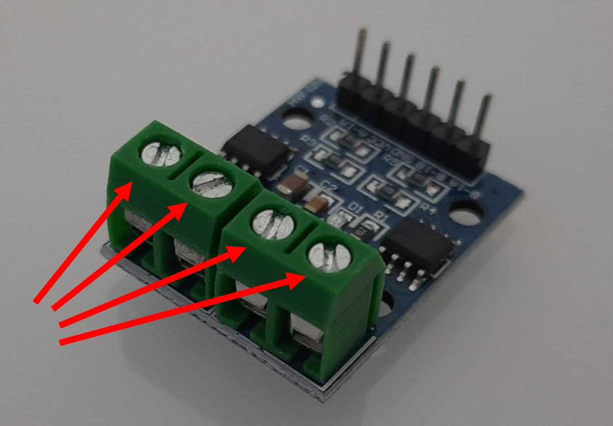
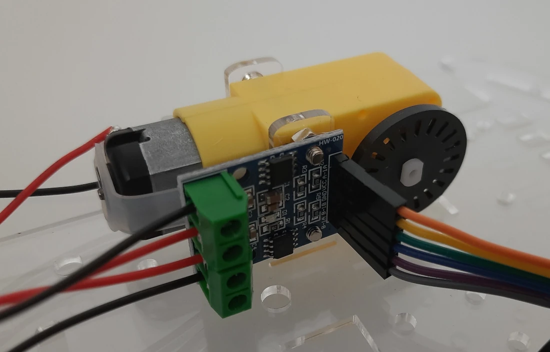
Prepare the L9110s motor drive module by opening the contacts where the motor cables will go:
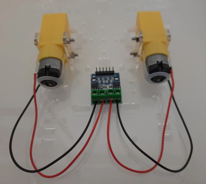
Connect the motor cables to the motor driver:
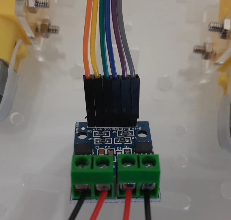
Now, please use 6 Dupont cables to connect the Raspberry PI Pico side of the L9110s motor drive module. I suggest you to use the same wire-colour order so that it will be simpler to connect them correctly to the Pico:
Fix the motor driver to one of the 2 motors, by using the motor driver holes near the Dupont connectors. You can also put the wheels internally to the motors (the black disk in the image), even if I really don’t know the meaning in this project as there isn’t a speed meter in this smart car… But you will be able in the future to add it if you want:
Fix the double-pass copper column on the acrylic board with 4 of the shortest screws:
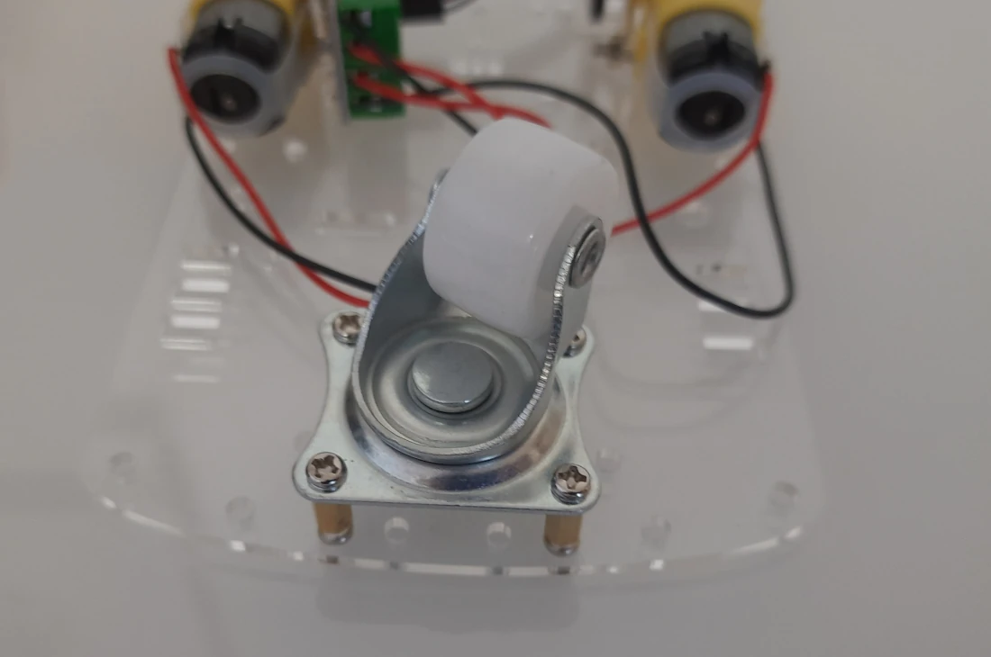
With 4 more screws having the shortest length, please fix the universal wheel:
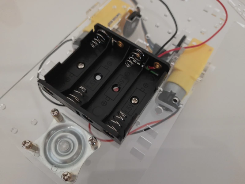
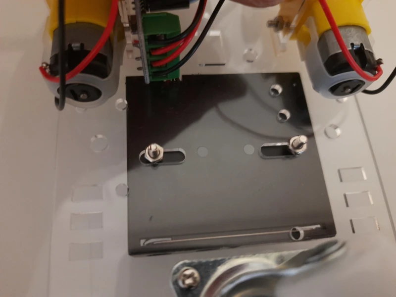
Assemble the Battery Case
Fix the battery box with 2 of the medium-size screws and their nuts, as shown in the following pictures:
Connect the Parts
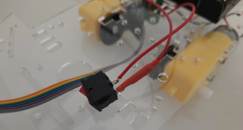
The following step is connecting the power button. This button must be connected to the positive pole of the battery pack (the red cable coming from the battery pack) and the VCC line of the breadboard (where the Raspberry PI Pico VSYS is connected too). Also this step requires a bit of soldering to fix the cables to the power button. Moreover, I wasn’t able to find a power cable in the box, so I re-used one of the Dupont wirings for the scope.
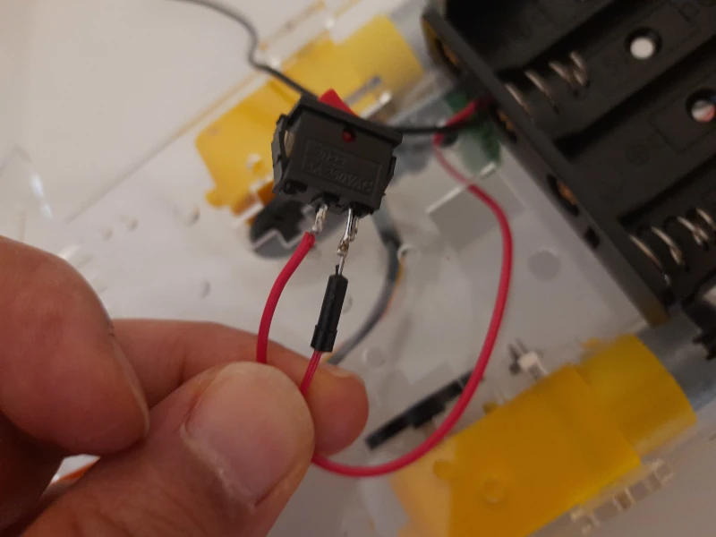
because of the unconventional wire, I also used a heat shrink to make it safer:
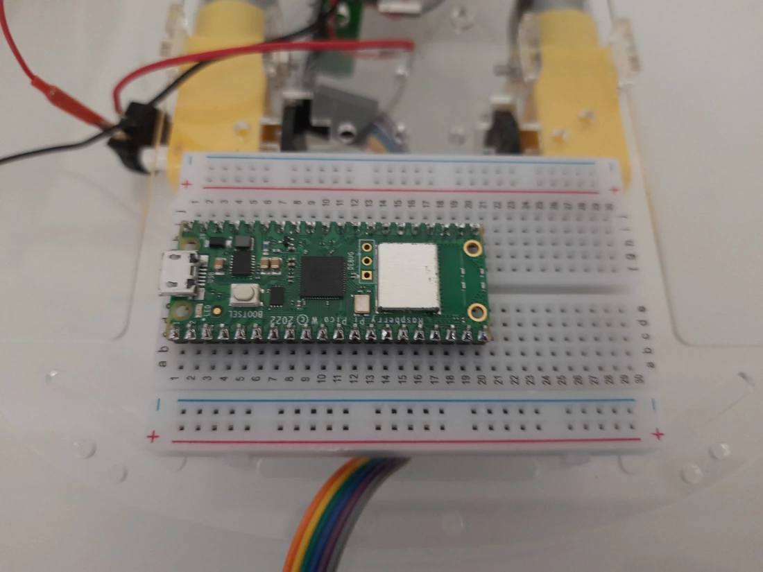
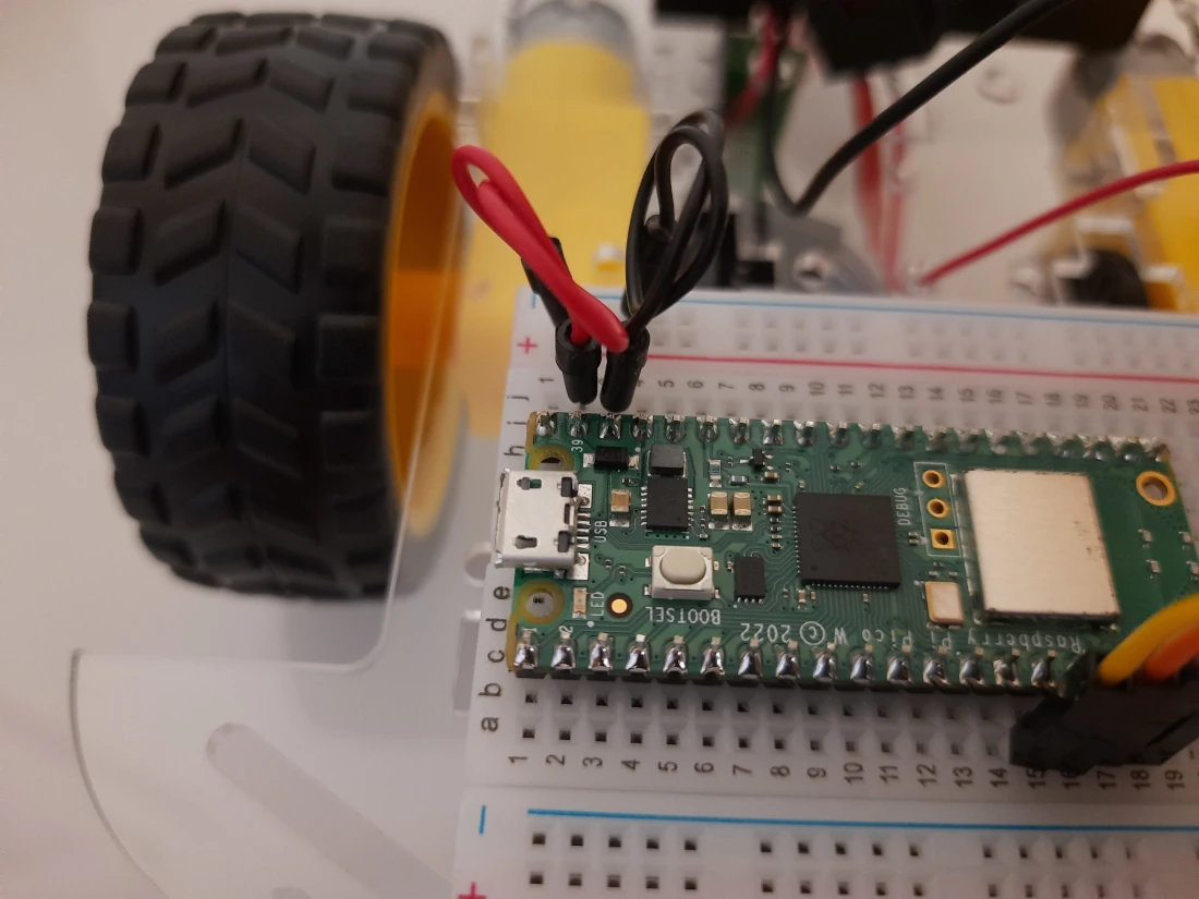
We can now place the Raspberry PI Pico in one of the breadboard and attach it to the smart car. Please note that, differently from the official tutorial, I prefer having the Raspberry PI Pico micro-USB port at the border of the breadboard, so that I can access it without problems when connecting it to my PC:
Now we can place the wheels:
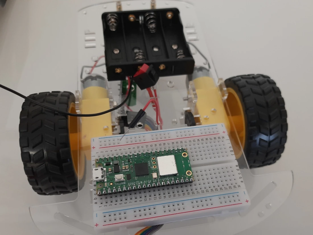
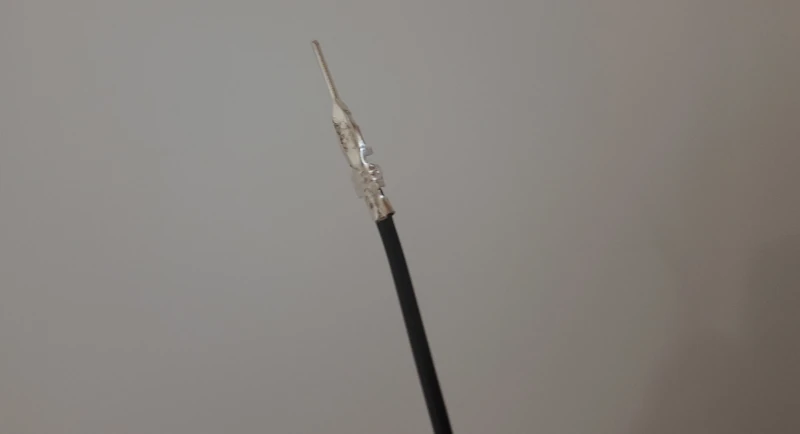
Finally, we can connect the cables. Here I found a new “problem”, as the GND (black) cable coming from the battery pack hasn’t a connector able to put it into the breadboard. I fixed this with one of my headings:
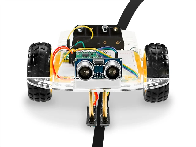
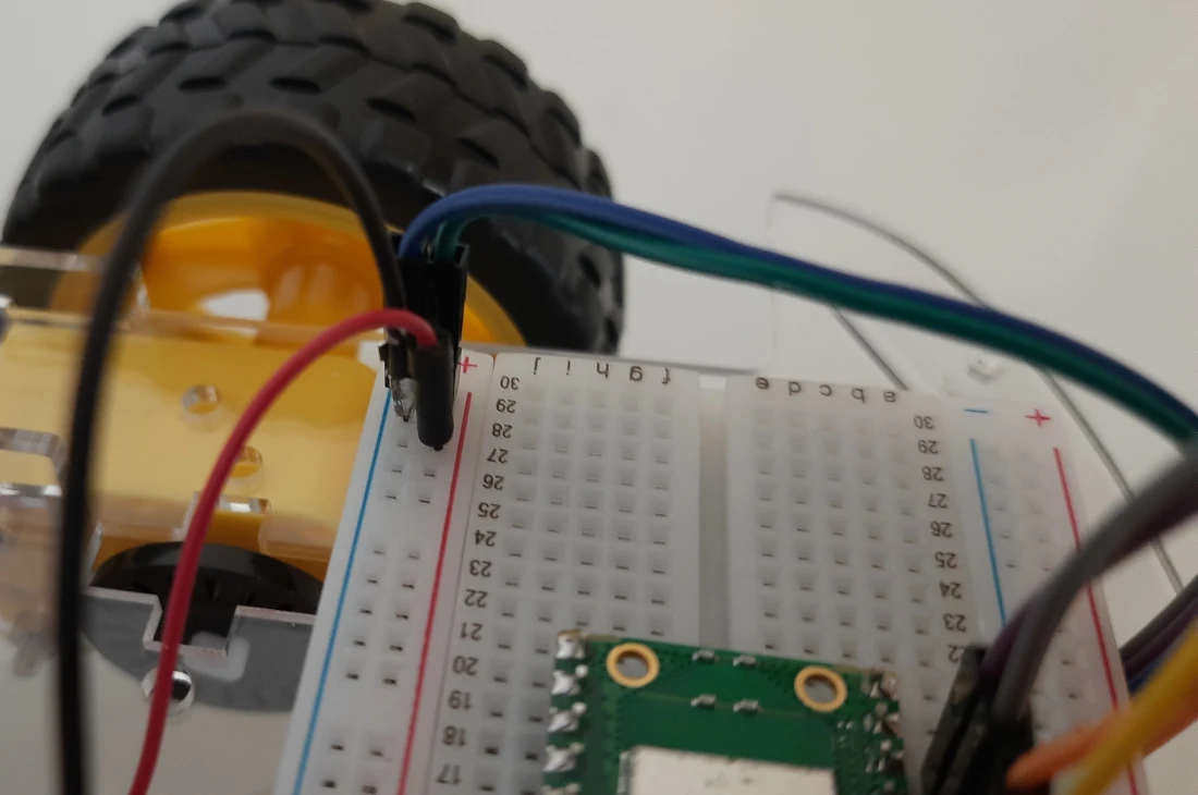
Now we can connect all the cables, as shown in the following pictures:
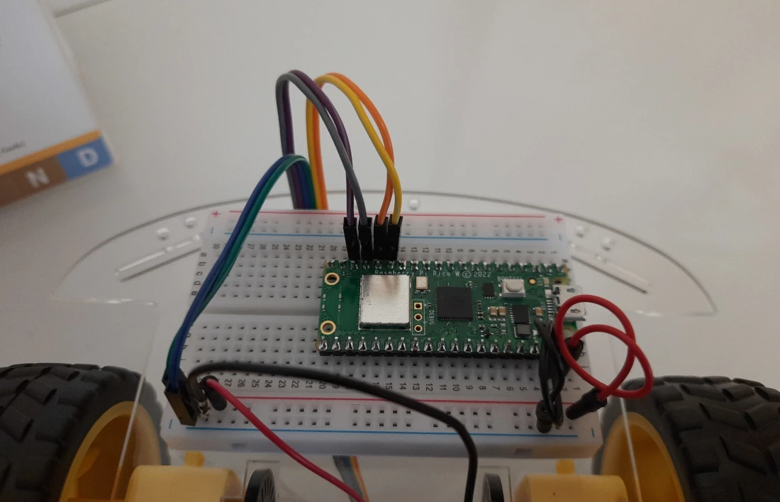
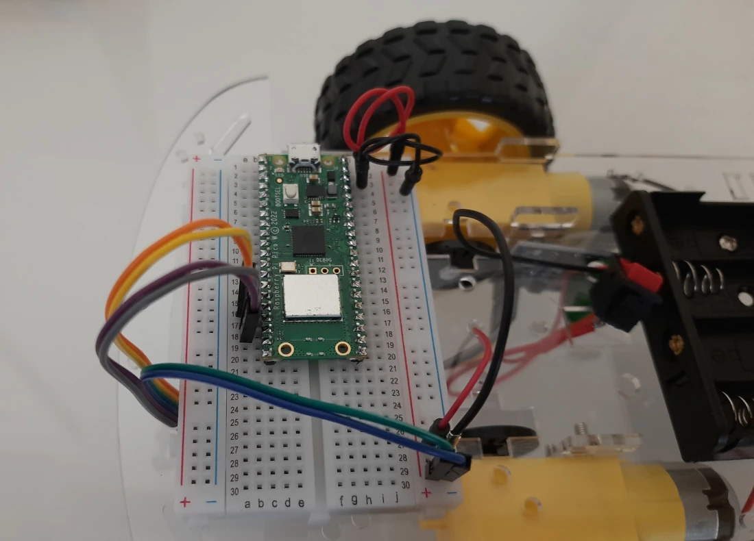
Wiring Table
To have a more clear wiring schema, please find the following table that will probably help you with the wire colors, based on the Raspberry PI Pico Pinout:
| L9110s motor drive | Raspberry PI Pico | power battery / power button |
|---|---|---|
| B-1A (grey cable) | GP12 | |
| B-1B (violet cable) | GP13 | |
| GND (blue cable) | GND | GND (black cable) |
| VCC (green cable) | VSYS | VCC (red cable coming from the power button) |
| A-1A (yellow cable) | GP10 | |
| A-1B (orange cable) | GP11 | |
Using the Smart Car
The smart car can be tested with different programs and adding different sensors to it, according to the examples provided in the Elecrow user manual. Please note that they also provide the code files from the Raspberry PI Pico Advanced Kit page, in the section “Manual&Lessons External Link”.
Final Opinion
The Elecrow Advanced Kit is surely worth getting as it brings you a wide number of sensors at an affordable price. Also, having a medium-advanced project as the smart car will make this kit more stimulating to joung people wishing to approach at their very first microelectronics and programming projects.
There are some improvement suggestions to Elecrow to get this kit even better:
- I suggest changing the current motors / power button with parts having pre-soldered cables. It is always a undesiderable job for beginners and advanced people to start soldering, moreover if they don’t have a soldering iron at home, with their kit in their hands
- Change the screwdriver with one having a smaller diameter (just a bit), as the one included in the kit doesn’t allow people, for example, to manage the screws in the motor driver
- Keep a revision of the kit parts, I found missing a wire to connect the power button to VSYS. It’s always better adding an additional, spare cable to the kit for the battery
- I found the hole for the power button too small compared to the button itself, there’s a need to review this too
What’s Next
Now that you know what are the Raspberry PI Pico PINs, you can use my Raspberry PI Pico tutorials for useful and funny projects!
Enjoy!

Open source and Raspberry PI lover, writes tutorials for beginners since 2019. He's an ICT expert, with a strong experience in supporting medium to big companies and public administrations to manage their ICT infrastructures. He's supporting the Italian public administration in digital transformation projects.
![]()
![]()
![]()
![]()
![]()
![]()
![]()