
Last Updated on 28th August 2025 by peppe8o
In this tutorial, I’m going to show how to identify and map ports on Raspberry PI Pico pinout.
The Raspberry PI Pico brings to RPI fans a lot of new ports, compared to the computer boards. One of the most appreciated features is that we can have analog ports (needed for many sensor projects). Let’s see more closely Raspberry PI Pico pinout
The new Raspberry PI Pico has 40 unpopulated PINs for your project, plus 3 additional PINs for debug purposes.
A common need is adding 20-pin strips for each side so that connecting your RPI Pico to a breadboard or wiring will be simpler. Soldering these strips requires a bit of attention, as working with a hot soldering iron can drive burns risk. A good guide to correctly solder these pins is available from MagPI How to solder GPIO pin headers to Raspberry Pi Pico tutorial.
This tutorial will not cover the first steps with Raspberry PI Pico, as you can find these guides in the following:
- First steps with Raspberry PI Pico for Beginners -> for Raspberry PI Pico
- Getting Started with WiFi on Raspberry PI Pico W and MicroPython -> for Raspberry PI Pico W
Raspberry PI Pico PINs Map
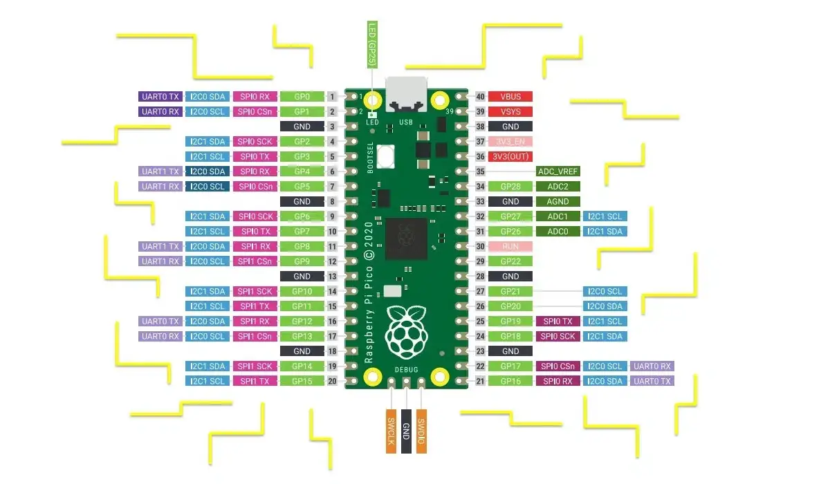
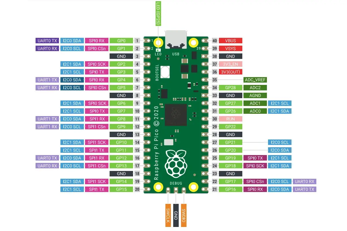
The Raspberry PI Pico pinout comes with a GPIO mapping completely different from common Raspberry PI boards. The following picture shows the official map for the Pico version without WiFi:
On the other hand, the Raspberry PI Pico W adds an Infineon CYW4343 WiFi module. This brought the Foundation to adopt a slightly different layout:
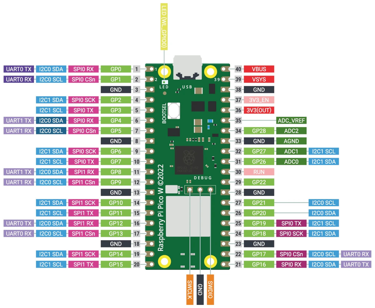
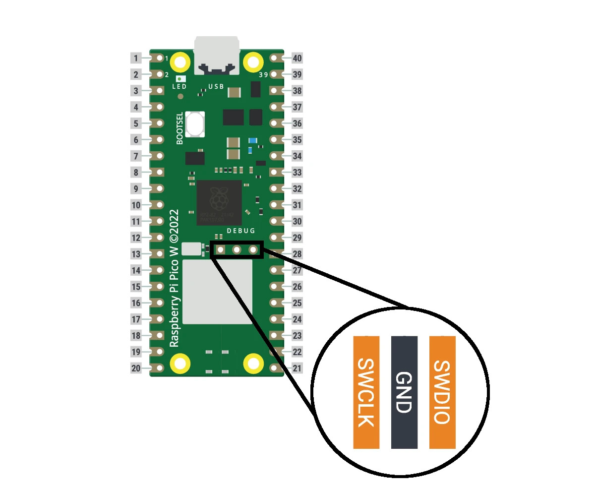
As you can see, there are really small differences between the two layout. The WiFi module moved the debug PINs (SWDIO, GND, and SWCLK) to a more central position. The LED PIN was connected to GP25 and now has a different connection and can be referenced in the MicroPyton code as “LED” pin.
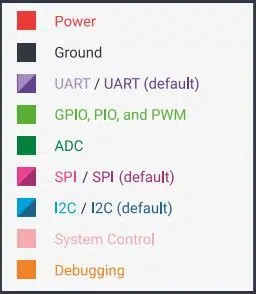
For both Raspberry PI Pico pinouts, the color of the labels can be interpreted with the following legend:
Besides the physical numbering, we can find the logical PINs number (GPnn, where “nn” goes from 0 to 28).
Some GPIOs are present even if not physically accessible and are used for internal board functions:
- GPIO29 – in ADC mode (ADC3), used to measure VSYS/3
- GPIO24 – VBUS sense (high if VBUS is present, else low)
- GPIO23 – Controls the on-board SMPS Power Save pin
We have 8 ground PINs (GND), from where the physical ground can be connected.
The following descriptions will be valid for both Raspberry PI Pico and Raspberry PI Pico W.
Power Pins
On the top-right side of RPI Pico, we have PINs giving a reference for high-level power:
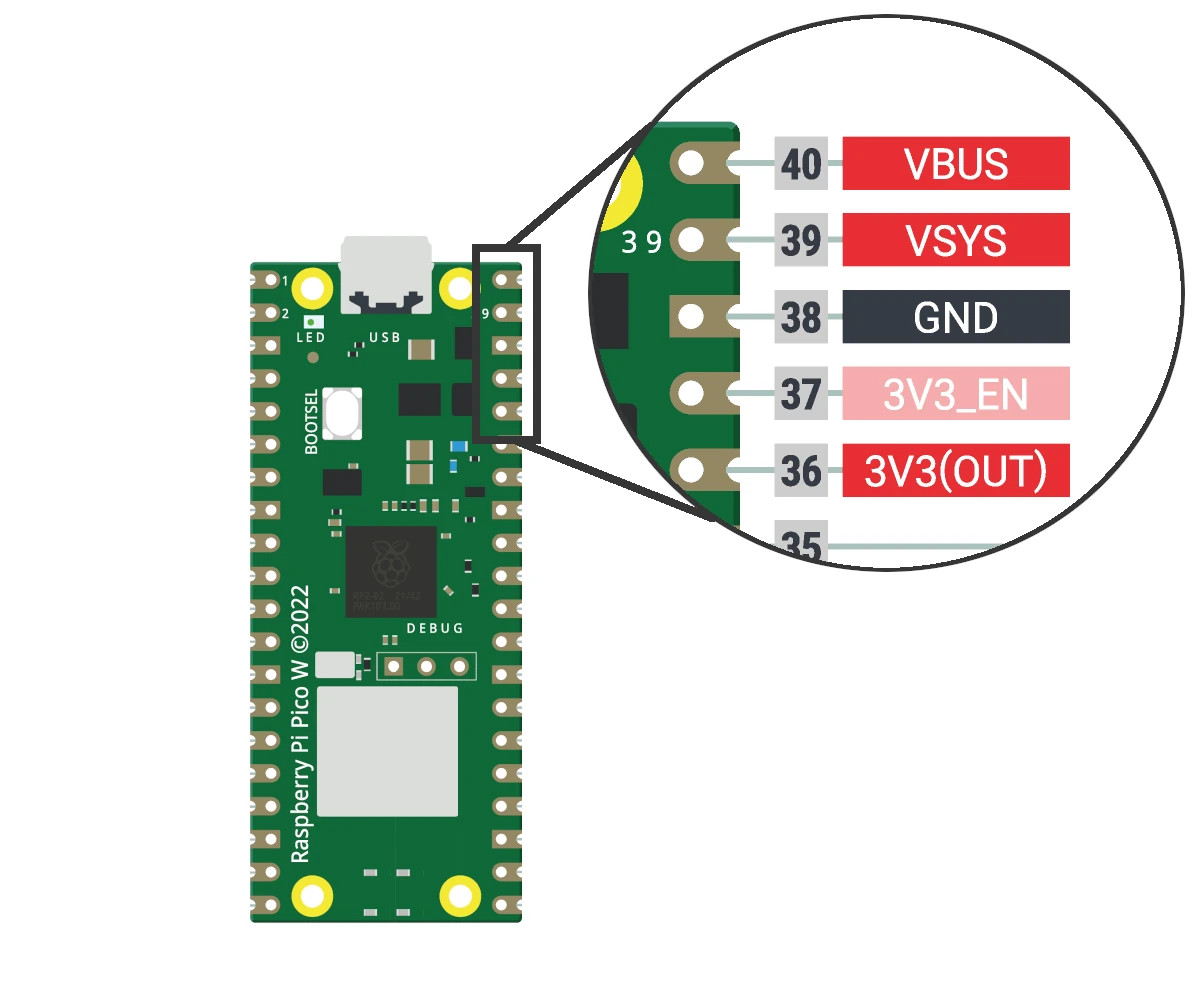
According to Raspberry PI Pico datasheet:
- VBUS is the micro-USB input voltage, connected to micro-USB port pin 1. If you use a 5V power supply from USB, this will be nominally 5V (or 0V if the USB is not connected or not powered).
- VSYS is the main system input voltage, which can vary in the allowed range of 1.8V to 5.5V, and is used by the onboard SMPS (Switched Mode Power Supply) to generate the 3.3V for the RP2040 and its GPIO.
- 3V3_EN connects to the onboard SMPS enable pin and is pulled high (to VSYS) via a 100K resistor. To disable the 3.3V (which also de-powers the RP2040), short this pin low.
- 3V3 is the main 3.3V supply to RP2040 and its I/O, generated by the on-board SMPS. You can use this pin to power external circuitry (maximum output current will depend on RP2040 load and VSYS voltage, it is recommended to keep the load on this pin less than 300mA).
Regarding the current load, there’s a common question that quite all people will ask in their projects: how much current can Raspberry PI Pico GPIO source? For this topic, we can find part of the answer in the final rows of Table 623 of RP2040 datasheet. Here, we can see that the “Maximum Total IOVDD current”, which means the sum of the currents sourced from all the Raspberry PI Pico GPIO, should be limited to 50mA.
Moreover, good guidance is to keep the current sourced from every single GPIO not higher than 10mA and this is the same guidance also adopted from the Raspberry PI Foundation, even if not explicitly documented.
Analog PINs
The RPI Pico does not have an onboard reference and therefore uses its own power supply as a reference from its SMPS (3.3V). This is a simple solution which has some minor drawbacks which shouldn’t interfere with common hobbyist purposes. You can use the ADC_VREF pin with an external reference if you need better ADC performance.
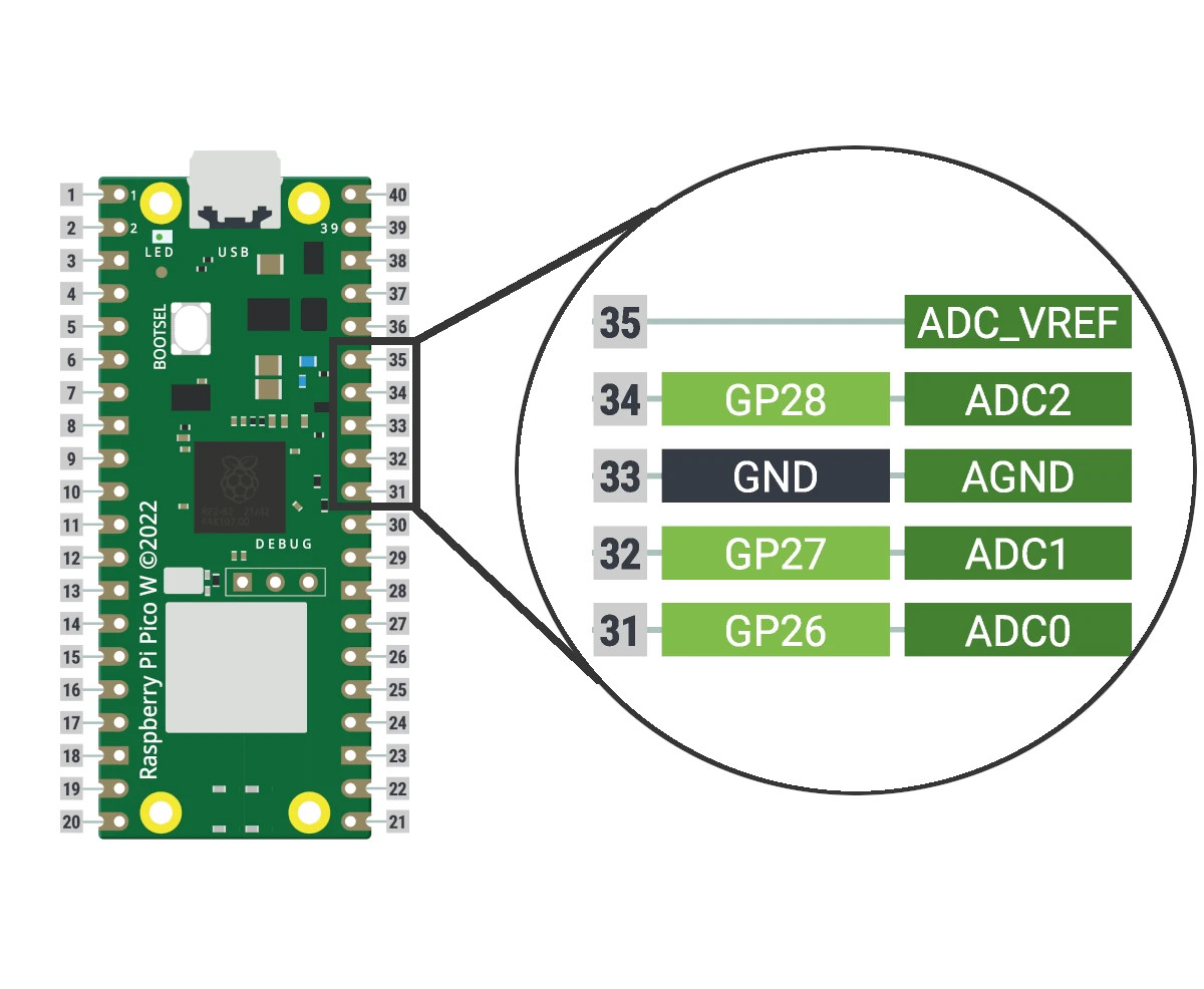
AGND is the ground reference for GPIO26-29, as analog ground plane is separated from other ones. You can connect this pin to digital ground if ADC performance is not critical for your project.
You can use the 3 ADC pins (ADC0, ADC1 and ADC2) for programming. They have a 12-bit logic, which means that signals from AGND to ADC_VREF are divided into 4096 levels.
PWM PINs
Raspberry PI Pico has 8 PWM blocks, each one driving two PWM output signals, for a total of up to 16 controllable PWM outputs (ref. to paragraph 4.5 from RP2040 datasheet). You can drive all the 30 GPIO pins by PWM blocks:
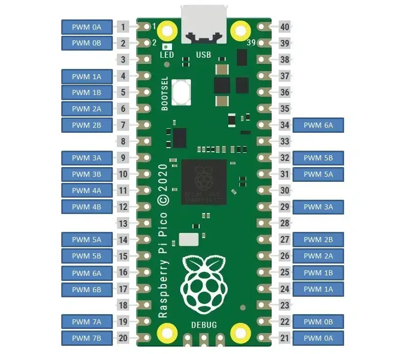
This means that when you set a defined PWM on PWM 2A, this signal will be available both on PIN 6 and 26.
If a PWM B pin is used as an input and is selected on multiple GPIO pins, then the PWM slice will see the logical OR of those two GPIO inputs.
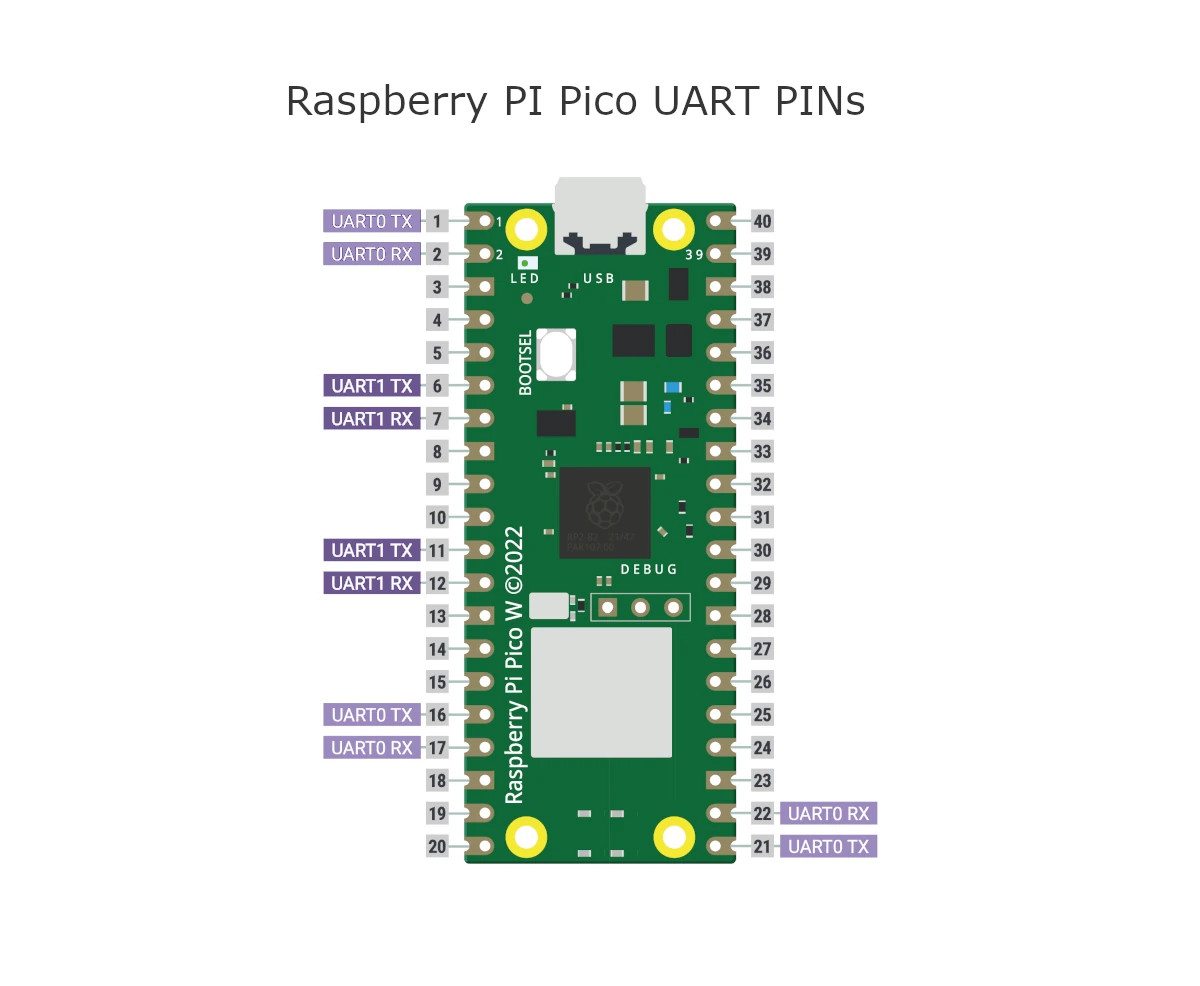
Digital Peripherals Interfacing
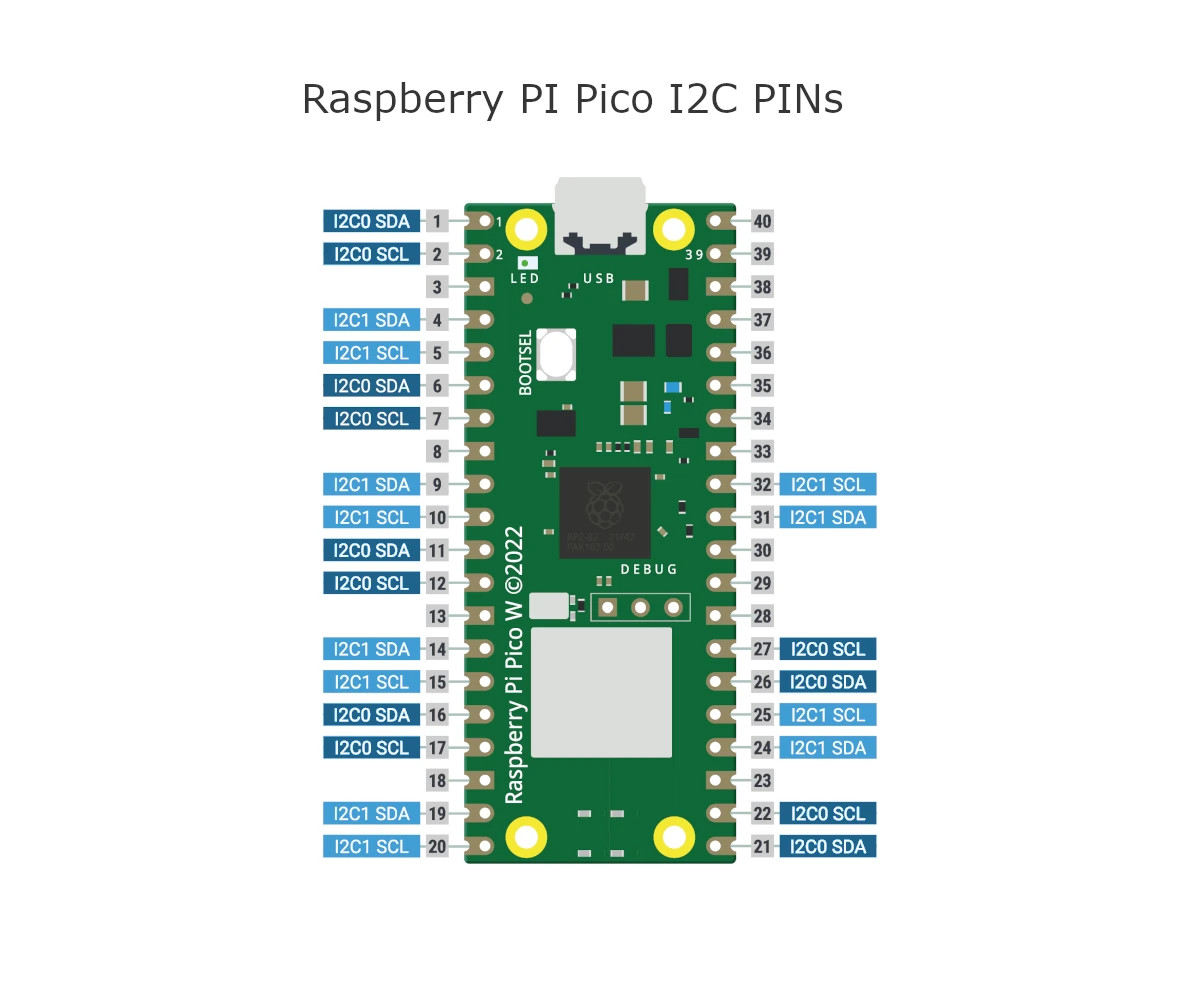
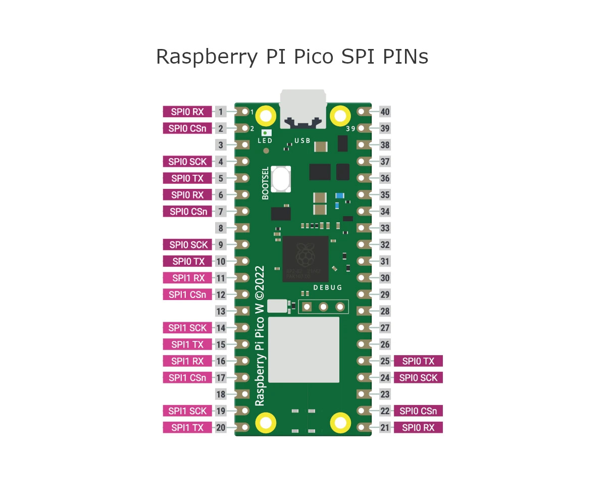
Raspberry PI Pico includes the capability to interface digital peripherals able to communicate using I2C, UART, or SPI:
RPI Pico supports up to 2 × UART, 2 × I2C, 2 × SP.
The UART allows communicating with enabled devices by performing the serial-to-parallel conversion on data received and parallel-to-serial conversion on data transmitted.
The I2C uses a 2-wire interface to connect devices for low-speed data transfer with the SCL (clock) and SDA (data) wires.
SPI is a serial peripheral interface using a 4 lines communication: Serial Clock, transmission, receiving, and chip select (this one to define who is master and slave in the communication).
Debug PINs
Besides managing and programming via a USB connection, the Raspberry PI Pico pinout also includes Serial Wire Debug (SWD) port. This allows resetting your board and running code without the need of pressing any button.
This port can be also useful to interact with the RP2040 for debugging.
Final Thoughts on Raspberry PI Pico Pinout
In conclusion, learning about the Raspberry Pi Pico pinout is an essential skill for anyone looking to work with this microcontroller. The pinout provides a map of the Pico’s physical connections, allowing you to easily connect external components and peripherals to your project.
By understanding the pinout, you can access the full range of features and capabilities of the Pico, including controlling LEDs, motors, sensors, and other components. You can also use the pinout to connect the Pico to other devices, such as other Raspberry Pis or Arduino boards.
Overall, understanding the Raspberry Pi Pico pinout is an essential step in becoming proficient with this microcontroller. With this knowledge, you can create complex projects and applications that leverage the full power of the Pico, and unlock a world of possibilities in the exciting field of electronics and programming.
What’s Next
Now that you know what are the Raspberry PI Pico PINs, you can use my Raspberry PI Pico tutorials for useful and funny projects!
Enjoy!

Open source and Raspberry PI lover, writes tutorials for beginners since 2019. He's an ICT expert, with a strong experience in supporting medium to big companies and public administrations to manage their ICT infrastructures. He's supporting the Italian public administration in digital transformation projects.
![]()
![]()
![]()
![]()
![]()
![]()
![]()

The chip select (CS) in SPI is not meant to define which party is master and which one is slave. It is a pin that master uses to tell which slave should listen to the communication. It allows to decide which of the slaves should listen to next commands.