
Last Updated on 13th April 2024 by peppe8o
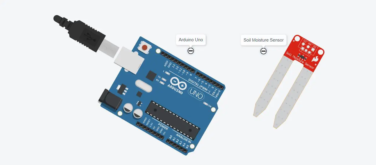
In this tutorial, we’ll interface the soil moisture sensor with Arduino Uno. This tutorial provides the coding, wiring diagram and component list for moisture sensors with Arduino.
To measure the water level of a pot plant, analog soil moisture sensor is good to use as its implant inside the soil to measure the level. It is good to use in an irrigation system and plants watering system
Soil Moisture Sensors Introduction
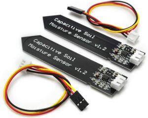
The soil moisture sensor uses to measure the water quantity in the soil. The amount of water in the soil can be measured by its moisture content. A soil moisture sensor comprises two conducting probes that function as a probe used to measure this quantity. Based on the variation in resistance between the two conducting plates, it can calculate the soil moisture content. The amount of moisture in the soil has an inverse relationship with the resistance between the two conducting plates. There are two types of sensors in the market known as capacitive and resistive. Only the difference is based on their measurement techniques. The resistive measurement happens on the basis of a change of resistance while the capacitive measure with a change in resistance. The Code of Arduino Uno for both remains the same.
Working Phenomena of Soil Sensor
We only need to affix the fork-shaped conductive probe to the soil because it includes two exposed conductive plates that function as a variable resistor, varying in resistance according to the soil’s moisture content. The probe’s resistance is inversely correlated with the soil moisture of the instrument. The conductivity of the soil improves with soil moisture, lowering resistance. The conductivity of the soil decreases with soil moisture content, which results in increased resistance. By detecting the resistance, this sensor generates an output voltage that allows us to calculate the moisture content.
What We Need
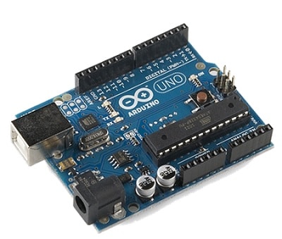
As usual, I suggest adding from now to your favourite e-commerce shopping cart all the needed hardware, so that at the end you will be able to evaluate overall costs and decide if to continue with the project or remove them from the shopping cart. So, hardware will be only:
Check hardware prices with the following links:


Step-by-Step Procedure
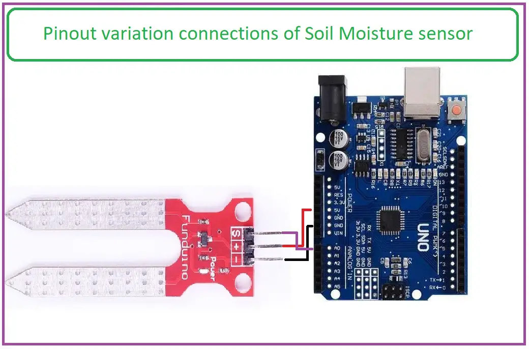
Wiring Diagram of moisture sensor with Arduino
In the circuit, the moisture sensor deals with the 5 V power PIN of Arduino. Please follow the wiring from the following pictures, according to Arduino Uno Pinout.
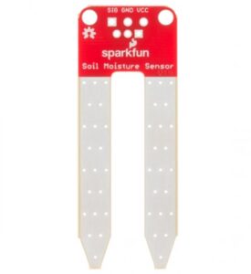
Depending on what sensor version you got, you may find different symbols in your hardware.
The first possible sensor labelling has a “S” (source), a “+”, and a “-” outputs. The wiring diagram will be according to the following:
- Source Pin = A0
- + Pin = connect to 5V.
- – Pin = Gnd
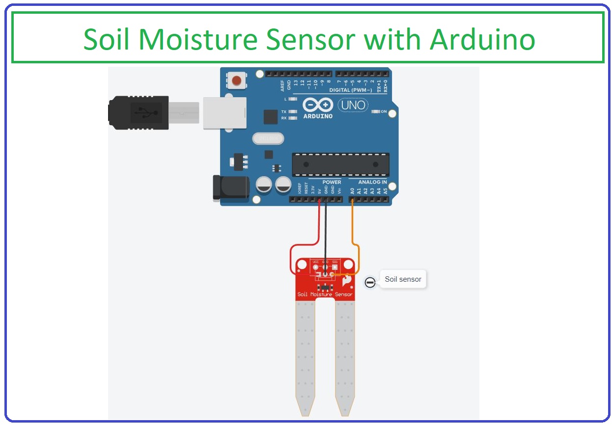
In the other cases, you should have a more classic case
- Soil sensor Vcc with Arduino PIN 5VCC
- Soil sensor GND with Arduino GND
- Soil sensor A0 with Arduino A0.
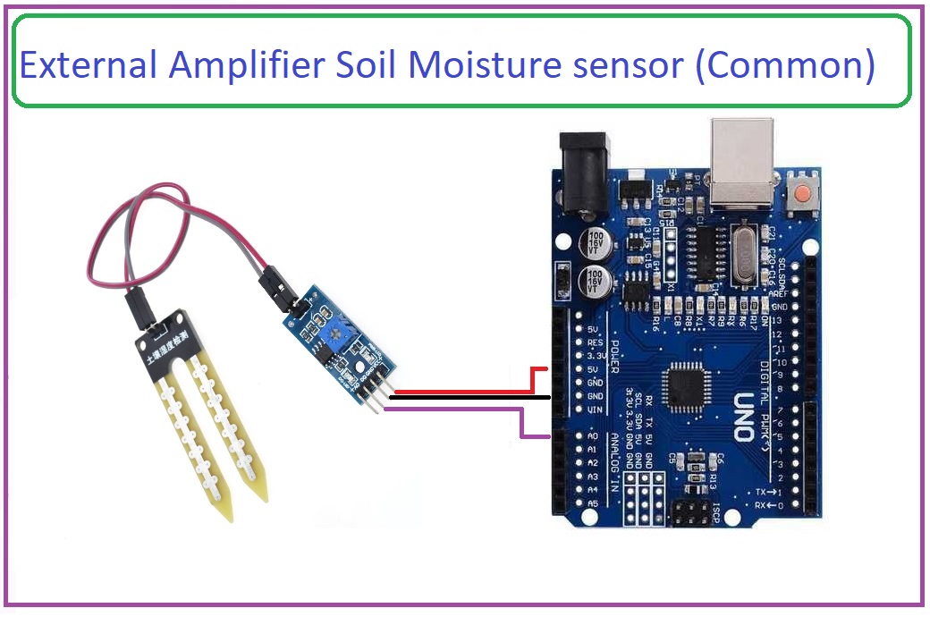
When you will use an amplifier, this will also bring to you 2 signal PINs: A0 and D0. The A0 is the analogic output and D0 is the digital output. You can use directly the analogic PIN, leaving the digital one disconnected:
- Soil sensor Vcc with Arduino PIN 5VCC
- Soil sensor GND with Arduino GND
- Soil sensor D0 not connected
- Soil sensor A0 with Arduino A0.
Get the code
Connect your PC to Arduino and open Arduino IDE. For the very first steps, you can refer to Connecting Windows PC with Arduino tutorial. You can get the .ino code and libraries from my download area with the following link:
Soilsensorcode.ino Explanation
Section 1: In this section, two variables are used to get the value of the sensor and convert it. The setup defines the serial monitor baud rate at 9600. While the pin of the analog is defined as the input to get the value. There are 6 pins of Arduino which are analog pins: A0 to A5.
int moisture = 0;
int percentage = 0;
void setup()
{ Serial.begin(9600); // serial monitor baud rate
  pinMode(A0, INPUT); // PinMode set, pin for moisture sensor
}
Section 2: In the loop section, the analog value of the sensor read is stored in the moisture variable. This value varies from 0 to 1023 which is mapped to 0 to 100 and stored in a percentage variable. The percentage is printed on the serial monitor after every 1 second.
void loop()
{
  moisture = analogRead(A0); // reading value
  percentage  = map(moisture, 0, 1023, 0, 100); // changing to percent
  Serial.print("Moisture= ");
  Serial.print(percentage); // Print percentage
  Serial.println("%");
  delay(1000);
}
Results
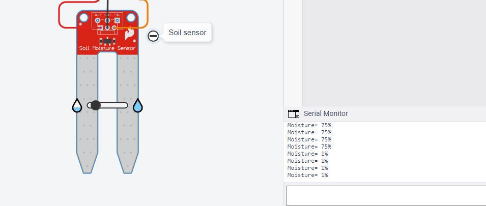
Results are shown from a simulation. In my simulator, the slider is moving to increase and decrease the water level. Results show that percentage is 75% and 1% on the serial monitor. This is achieved by moving the slider right and left respectively.
What’s Next
Please find more tutorials on Arduino in peppe8o Arduino archives.
Enjoy!
Umar Jamil
For any queries and help for work, please contact me at:
Whatsapp: +92-346-661-7017/ Link
Email: umarjamil0007@gmail.com

I'm an Electronic Engineer, well-skilled to solve the issues of hardware and software. I do have laboratory which contains unlimited sensors and modules for testing the working. Also, I am experienced in Arduino programming, Android mobile application, microcontroller programming, IOTs and embedded projects. I provide services to control, realize the sensor data in the Mobile Application. For any queries and help for work Contact: Whatsapp:+92-346-661-7017 Email: umarjamil0007@gmail.com
![]()


