
Last Updated on 2nd September 2023 by peppe8o
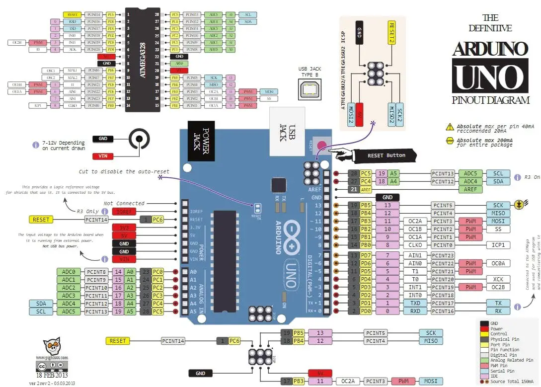
This tutorial will explain the pinout of the Arduino Uno. As different controls have unique working and communication protocols. Here, I’m going to explain in detail each pin group.
When we need a controller of best choice, Arduino Series is best choise as it has a wide community helping new users. When you use external devices or sensors, you will need to be aware of Arduino Uno Pinout.
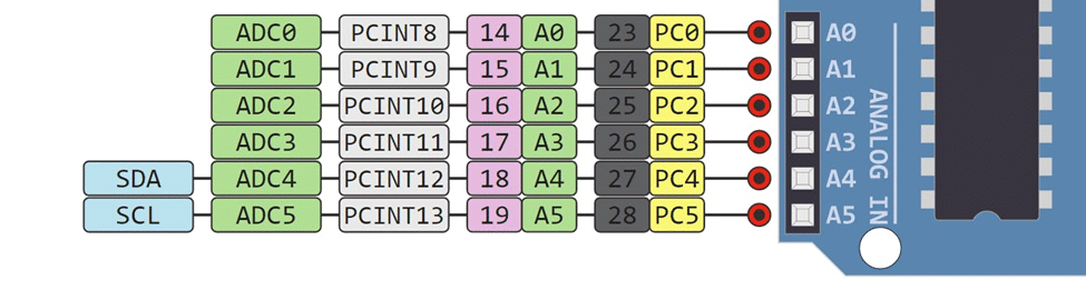
Arduino Analog PINs (6 pins)
Arduino Uno has six (6) analog pins that use ADC (Analog to Digital Converter). The beauty of these pins is their flexibility. You can use these pins both as analog inputs or digital input or output. Analog Pins (A0-A5) have the ability to read analog voltages. Arduino has 10 bit ADC which means that it can represent analog voltage by 1024 digital levels. ADC converts the analog voltage into bits and makes it readable for the microcontroller. To read an analog pin, your code will use analogRead(pin). .
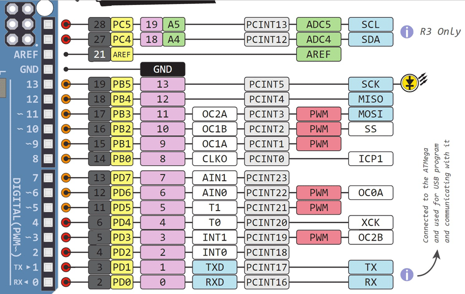
Arduino Digital PINS (All pins can be used)
You can configure digital Pins as either input or output. Digital pins are either On (High) which means 5volts and logic 1, or Off (LOW) which means 0 volts and logic 0. All the pins in Arduino UNO can be Pulled up by pinMode(pinName, INPUT_PULLUP); command. By using the command pinMode, a pin can be declared as input or output. When a pin is declared as an input, it receives a voltage between 0 to 5 volts which are converted to a digital representation equal to 0 or 1. There are two thresholds
- Below 0.8 volts means the logic 0.
- Above 2 volts means the logic 1.
You can use Arduino Uno Pin 0 to 13 digital pins either as input or output depending upon the requirement. Digital pins also have some of the PWM(Pulse Width Modulation) pins. The pins are marked with the sign (~). On Arduino Uno, PWM pins are 3, 5,6, 9, 10, and 11. Writing on the PWM pin analogWrite(pin) is used. To read and write a digital pin, your code will use digitalRead(pin) and digitalWrite(pin) respectively. Individually each pin can provide or sink the current of 40m Amps, but to be on a safer side 20m Amps is recommended. From all inputs, the maximum current that can be sunk is 200m Amps.
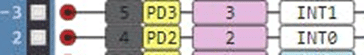
Arduino Hardware Interrupt PINS (Pin 2 and 3)
There are two external interrupt pins on Arduino, known as INT0 and INT1. Pin 2 and Pin 3 are the two pins on Arduino Uno which are dedicated to interrupts. These two interrupt pins have the highest priority after the reset button. Whenever the logic will be given to these pins, they will be given priority to execute.
Serial Communication
Serial communication allows to exchange of data between Arduino and other serial devices such as sensors, displays, etc. in Arduino Uno there are three serial communication interfaces namely UART, SPI, and I2C. UART communication occurs through pin 0 and pins 1. SPI is four wires interface comprising MISO, MOSI, SS, and SCK. MISO stands for Master in slave out. MOSI means Master out Slave in. SS is an abbreviation for slave select and SCK is a clock pin used to synchronize the data. I2C interface is known as a two-wire interface it contains two pins namely SDA and SCL. SDA is a data line where data is exchanged and SCL is the clock pin.
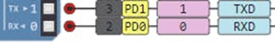
Arduino UART Pins
UART communication interface uses two pins, namely transmitter, and receiver, to exchange data with other devices. Pin 0 works as a receiver (RX), while Pin 1 works as a transmitter (TX). Software Serial library enables the user to use any two pins as transmitter or receiver.
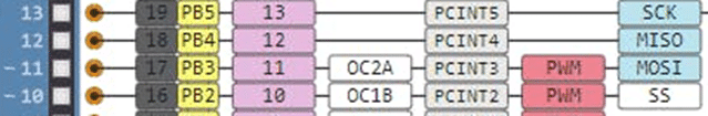
Arduino SPI Pins
Serial Peripheral Interface (SPI) serial data communication protocol allows communication with multiple devices. In such communication, one device works as the master, and the rest works as slaves devices.
Arduino Uno has the following SPI pins:
- MISO (Master In Slave Out): A pin which sends the data to master device. In Arduino Uno dedicated pin for MISO is Pin 12.
- MOSI (Master Out Slave In): This wire sends the data from Master to Slave. Pin 11 in Arduino Uno is a MOSI pin.
- SS (Slave Select): this pin determines which device is being communicated. Pin 10 on Arduino Uno is an SS pin.
- SCK: is the clock pin. In Arduino Uno, Pin13 works as clock pin.
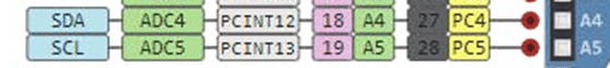
I2C Pins
I2C communication protocol, commonly known as the I2C bus or two-wire communication, has been introduced to reduce the number of wires in order to avoid the complexities in the circuits. As SPI requires four wires which brings the complexity in the circuit. If a fault in one wire of the SPI occurred it ends the communication. I2C on the other hand consists of two wires which minimize complexity.
Pin A4 and A5 work as SDA and SCL respectively.
SCL works as the clock line, designed for data synchronization.
SDA works as a data line, carrying data transmission or reception.
Each device has its own unique address and Arduino Uno can communicate with up to 128 devices on its bus.
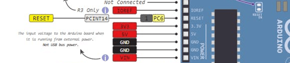
Power Pins
VIN Pin: This pin can power up the Arduino from an external power supply. At Vin pin maximum voltage applied is 9V.
5 V and 3V3 pin: These pins provide regulated 5v and 3.3 volts to external components. The maximum current which can be drawn from 5V is 200mA. while for 3.3V maximum current is 50 mA.
GND Pins: Ground pins complete the circuit.
Vref: V reference is used for the analog comparison. Suppose we are applied 1V and at analog 1v is applied at analog pin we 1/5 X1024: 204.5 will be detected. While for 1V applied at Vref 1/4X1023: 255.5 will be detected.
Enjoy!
Please find more tutorials on Arduino in peppe8o Arduino archives.
Umar Jamil
For any queries and help for work, please contact me at:
Whatsapp: +92-346-661-7017
Email: umarjamil0007@gmail.com

I'm an Electronic Engineer, well-skilled to solve the issues of hardware and software. I do have laboratory which contains unlimited sensors and modules for testing the working. Also, I am experienced in Arduino programming, Android mobile application, microcontroller programming, IOTs and embedded projects. I provide services to control, realize the sensor data in the Mobile Application. For any queries and help for work Contact: Whatsapp:+92-346-661-7017 Email: umarjamil0007@gmail.com
![]()


