
Last Updated on 3rd September 2024 by peppe8o
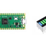
In this tutorial, I’m going to show you how to use the 74hc595 chip with a Raspberry PI Pico and MicroPython, in an easy configuration that drives 8 LEDs. I also will add an example code showing how to use it with a random LED effect.
Complex Raspberry PI Pico projects can require many connections with many sensors/devices so that the rich 40-PIN GPIO can become limited. In these cases you can get help from a simple and cheap electronic piece: the 74HC595 Shift Register, also known as Serial to Parallel Converter.
Plese note that if you want to connect this chip with a Raspberry PI computer board (like Raspberry PI Zero W, RPI 4 Model B and so on)you can refer to my Using 74hc595 Shift Register with Raspberry PI tutorial.
What is the Shift Register
The shift register chip has been already explained in detail in my Using 74hc595 Shift Register with Raspberry PI, so I’m not going to deep again its explanation. However, a brief refresh of how input and output are linked is useful to remind its use.
The shift register acquires a serial data flow from one of its PINs (data PIN), store these data and expose them in its 8 output PINs (Q0, Q1, …Q7).
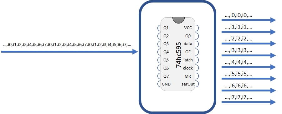
Each output pin can have 0 (off) or 1 (on) value. To set each of these values on or off, we feed in the data using the data and clock PINs of the chip in a precise timing diagram. The clock needs to receive nine pulses. At each pulse (on rising edge), if the data PIN is high then a 1 gets pushed into the shift register; otherwise, a 0.
When all eight pulses have been received, enabling the ‘latch’ pin stores those eight values to register and exposes them in output PINs.
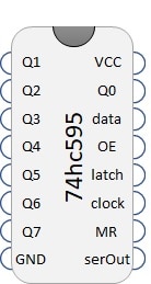
Beside output PINS (Q0…Q7), data, clock and latch, other PINS are exposed from 74hc595:
- Vcc and GND: of course, 5v and ground to power output
- OE (Output Enable): This PIN enables or disables output. 74hc595 exposes output when OE is low (0)
- MR (Master Reclear): This PIN cleans memory when put to 0. So, having 74hc595 working means MR connected to 1.
- serOut (Serial Output): is used when you need to drive a second shift register attached to this one.
What We Need
As usual, I suggest adding from now to your favourite e-commerce shopping cart all the needed hardware, so that at the end you will be able to evaluate overall costs and decide if to continue with the project or remove them from the shopping cart. So, hardware will be only:
- A common computer (maybe with Windows, Linux or Mac). It can also be a Raspberry PI Computer board
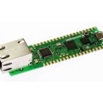
- Raspberry PI Pico microcontroller (with a common micro USB cable)
- Dupont Wiring
- Solderless breadboard
- Resistors
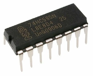
- 74HC9595 chip
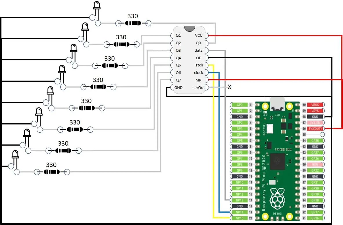
Wiring Diagram
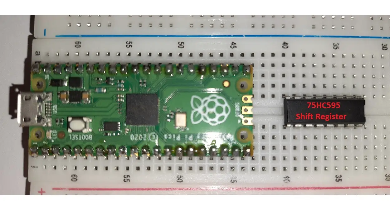
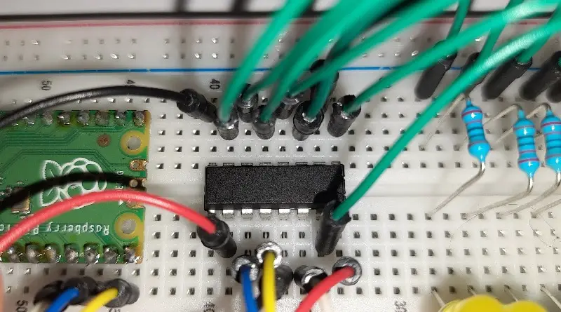
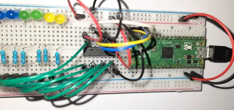
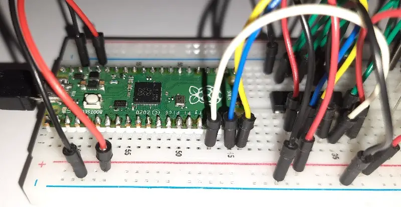
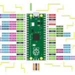
Please find in following picture the wiring diagram for this project. Note that LED longer PIN (positive) goes toward Shift Register. SerOUT remains unconnected. For microcontroller ports, you can refer my Raspberry PI Pico pinout article.
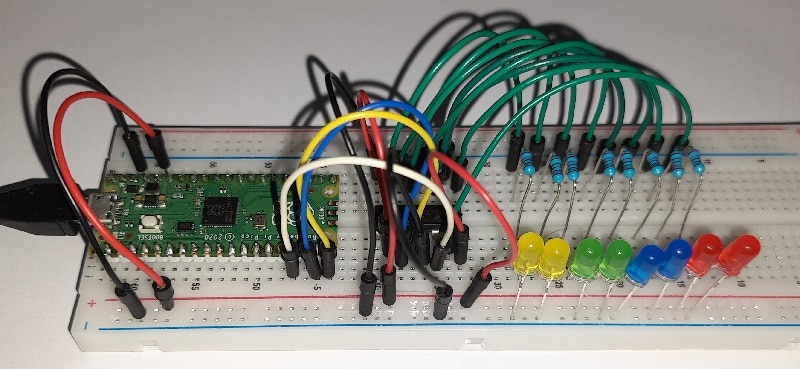
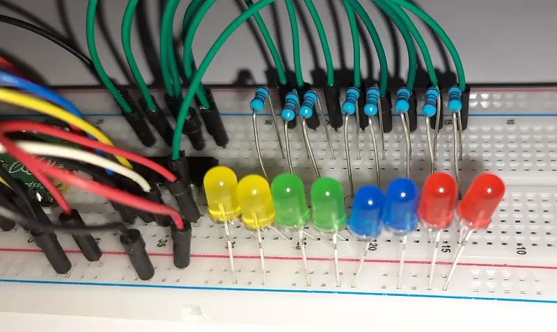
Please find below some pictures with details:
Step-by-step Procedure
Prepare cabling according to the previous paragraph. Connect RPI Pico to Thonny (you can refer to my tutorial about the First steps with Raspberry PI Pico).
Get and Understand my pico74HC595.py Code
Now download my main file to test your DHT11 sensor:
I’ll explain all code lines in the following paragraphs.
First of all, required libraries are imported:
from machine import Pin
import utime
import random
utime and random are not strictly required to use the 74hc595 shift register, but it is only required for our test example.
Then PIN are assigned to variables for better code management and understanding. These values match showed wiring diagram. If you use different GPs, please edit according to your cabling (ports number can be found in Raspberry PI Pico pinout):
dataPIN = 13
latchPIN = 15
clockPIN = 14
With next rows we accomplish two actions with each single line. Each line converts the dataPIN, latchPIN or clockPIN variable (which are simple integer numbers) into micropython PIN objects and set them to output:
dataPIN=Pin(dataPIN, Pin.OUT)
latchPIN=Pin(latchPIN, Pin.OUT)
clockPIN=Pin(clockPIN, Pin.OUT)
We use a function to manage the shift register update call. This function requires 4 parameters:
- input -> a string containing 8 chars composed only of “1” and “0”
- data -> to identify data transmission PIN
- clock -> to identify clock signal PIN
- latch -> to identify latch PIN
This function also manages clock signal before and after each step:
- latch to zero,
- data transmission
- latch to 1
We transmit data in reverse order because Q7 output must enter the data port first, followed by other data according to timing diagram.
def shift_update(input,data,clock,latch):
  #put latch down to start data sending
  clock.value(0)
  latch.value(0)
  clock.value(1)

  #load data in reverse order
  for i in range(7, -1, -1):
    clock.value(0)
    data.value(int(input[i]))
    clock.value(1)

  #put latch up to store data on register
  clock.value(0)
  latch.value(1)
  clock.value(1)
With this function available, if you want (for example) to set all outputs to 0 you can use simply:
shift_update("00000000",dataPIN,clockPIN,latchPIN)But our test code also implements a usage example. This example starts from a configuration with all LEDs off. Then starts an infinite loop generating at each iteration a random number (0 or 1) and assigning it to Q0. All other outputs are shifted by one position, so the previous Q0 value becomes Q1, Q1 goes to Q2 and so on, with Q7 value disappearing. Finally we set a time delay to make this effect visible to human eyes:
bit_string="00000000"

while True:
    shift_update(bit_string,dataPIN,clockPIN,latchPIN)
    bit_string = str(random.randint(0, 1))+bit_string[:-1]
    utime.sleep(0.3)
Running the pico74HC595.py Script
Run this script in your Thonny IDE (F5) and your LEDs will start with a result similar to the one from the following youtube video:
What’s Next
Interested to do more with your Raspberry PI Pico? Try to look at my Raspberry PI Pico tutorials for useful and funny projects!
Enjoy!

Open source and Raspberry PI lover, writes tutorials for beginners since 2019. He's an ICT expert, with a strong experience in supporting medium to big companies and public administrations to manage their ICT infrastructures. He's supporting the Italian public administration in digital transformation projects.
![]()
![]()
![]()
![]()
![]()
![]()
![]()

Hi
Thanks for posting this. I have your program running fine but I am puzzling over whether it is really necessary to convert the bit sequence to a string before loading the bits on to the data pin of the 74HC595.
That said, I have just noticed an error in your write up. Towards the end, just before the link to your sample pico74HC595.py code, you have written:
“Now download my main file to test your DHT11 sensor:
!! Not a big deal but might cause some confusion, so you might want to fix this!
(Incidentally I have obtained a DHT11 and I got it working without too much difficulty.)
Cheers
Me again.
So I have figured out a slightly simpler way to get the control bits into the DATA pin without using string representations. Here is my code for the shift_update() function and how to call it.
def shift_update(data_bits, data, clock,latch): # Here data_bits is an integer; using “input” for this
# argument is probably not a good idea, as “input”
# seems to be a reserved word
#put latch down to start data sending
clock.value(0)
latch.value(0)
# clock.value(1) # Not needed? It just gets set to 1 and immediately set back to 0
#load data in reverse order
for i in range(7, -1, -1):
clock.value(0)
data.value(data_bits & (1 << i)) # Use bitwise operators directly on the input value
clock.value(1)
#put latch up to store data on register
clock.value(0)
latch.value(1)
clock.value(1)
#main program, calling shift register() function
while True:
bit_pattern = urandom.randint(0, 255) # This is actually more like a genuine random number
shift_update(bit_pattern, dataPIN, clockPIN, latchPIN)
utime.sleep(0.3)
Hi David, sorry for the late reply.
Every code logic can be expressed in several ways, all working. Working with strings, you can convert the value, before passing t function, with the str() python operator.
The clock value to 1, just before the revert to 0 at the start of function, is required according to shift register working diagrams.
Regarding the confusing phrase, please can you help me understanding what was the misunderstanding, so that I can improve it?
Many thanks for your feedback!
Hi!
Thanks for responding. Absolutely no problem about a late reply! For sure, there are many ways to skin the coding cat…. but in general whatever runs fastest is best. I really doubt that creating strings from ints and then converting the strings back to single bit integers to load the data register can be as fast as creating an int and loading its bits directly.
Interesting that setting the clock value to 1 and then reverting to 0 is required. My code runs perfectly well with that line commented out.
The confusion I mentioned is simply that you evidently copied and pasted a text from another article which was about the DHT11 humidity sensor! So your text about getting code for programming a multiplexing circuit actually says:
“Now download my main file to test your DHT11 sensor:”
Like I said, it’s not a big deal but it could cause confusion.
Thanks for all your efforts on this. It is immensely helpful to people like me getting up the microPython learning curve.
Hi, how can manage 3 or n shift register???
Hi GioH.
To manage multiple Shift registers, you can put them in serial connection or in parallel.
In serial connection, you attach the serialout of first SR to data of second and so on. Latch for allow SR are connected together, same forclock. You can use my code, running it as times as the number of connected SR:at the first update you load data for last SR, then you update data for the prev one and so in up to the first.
Parallel configuration require one GP for each data, while clock and latch are still together. In this case you need to change my code.
For quite all project, the serial configuration is the best option as the SR are so fast that user will never see intermediate effects
Thanks a lot peppe8o. Works like a charm… thanks for help.
I’ve made the same circuit and trying to make it work, but it behaves really strange. Only led connected to Q0 lights up. When I remove any other led (just connecting using resistor), all start working properly (just without that disconnected led).
Any ideas what am I doing wrong? Thank you.
It seems to me that the power passed to the Pico may not be enough in your case. Try changing the power source
Yeah, I thought it could be power, so replaced Pico with buttons, and attached 5V source. Clicking the buttons I can make diods blinking, still situation is the same… It works only when any 7 of them are connected (except q0)… I think this 74hc595 can be just broken
Please, can you send me a photo of your wiring? Send it to my email address: giuseppe@peppe8o.com
I modified the code so that it uses 16 LEDs/2 shift registers and uses a virtual timer to control the animation. This way you can keep control of the REPL. I also changed it so that it uses the default SPI pins on the Pi Pico. The code isn’t all that different.
**********************************************
from machine import Pin, Timer
import random
#define PINs according to cabling
dataPIN = 19
latchPIN = 17
clockPIN = 18
#set pins to output PIN objects
dataPIN=Pin(dataPIN, Pin.OUT)
latchPIN=Pin(latchPIN, Pin.OUT)
clockPIN=Pin(clockPIN, Pin.OUT)
bit_string=”0000000000000000″
#define shift register update function
def shift_update(tim):
# get the previously defined global values.
global bit_string
global dataPIN
global clockPIN
global latchPIN
#put latch down to start data sending
clockPIN.value(0)
latchPIN.value(0)
clockPIN.value(1)
#load data in reverse order
for i in range(15, -1, -1):
clockPIN.value(0)
dataPIN.value(int(bit_string[i]))
clockPIN.value(1)
#put latch up to store data on register
clockPIN.value(0)
latchPIN.value(1)
clockPIN.value(1)
bit_string = str(random.randint(0, 1))+bit_string[:-1]
def main():
#start the timer, calling shift register function as a callback
Timer(-1).init(period=100, mode=Timer.PERIODIC, callback=shift_update)
if __name__==”__main__”:
main()
Thank you for your feedback and for the proposed code alternative, David!
Thank you for your good idea. I use it in a python script to illuminate colored LEDS 20000lux (20mA) and it’s OK.
To simplify I create a library file. I don’t think it’s necessary to give data, clock and latch as arguments during the update.
The library in a file lib74HC595.py
from machine import Pin
import utime
class 74HC595:
”’
Classe class_74HC595
8-bit serial-in/serial or parallel-out shift register with output latches; 3-state
”’
#
#
#
def __init__(self, dataPin, latchPin, clockPin): #
”’
Constructeur :
On y défini les trois signaux de commande du shift register
”’
self.dataPIN = Pin(dataPin, Pin.OUT)
self.latchPIN = Pin(latchPin, Pin.OUT)
self.clockPIN = Pin(clockPin, Pin.OUT)
def update(self, input):
”’
Mise à jour du shift register selon les data dans input
”’
#put latch down to start data sending
self.clockPIN.value(0)
self.latchPIN.value(0)
self.clockPIN.value(1)
#load data in reverse order
for i in range(7, -1, -1):
self.clockPIN.value(0)
self.dataPIN.value(int(input[i]))
self.clockPIN.value(1)
#put latch up to store data on register
self.clocPINk.value(0)
self.latchPIN.value(1)
self.clockPIN.value(1)
Usage in script Raspberry Pico
from lib74HC595 import class_74HC595
..
# Instantiation d’un objet de type 74HC595
shiftRegister = class_74HC595(dataPin, latchPin, clockPin)
# Initialisation (Le shitRegister est en mode Common Anode, Inversion)
bit_string=”11111111″
shiftRegister.update(bit_string)
… later
bit_string=”00000000″
while True:
update(bit_string)
bit_string = str(random.randint(0, 1))+bit_string[:-1]
utime.sleep(0.3)
Thank you for your feedback, Jean-Pierre. Please send me the pictures of your project if you want to share it with peppe8o’s readers 😉