
Last Updated on 9th June 2024 by peppe8o
Raspberry PI GPIO ports are a really useful resource and allow PI to interface real world with a wide number of external sensors. However, some projects requires so many connections with many sensors/devices that the rich 40-PIN GPIO can become limited. In these cases you can get help from a simple and cheap electronic piece: the Shift Register or Serial to Parallel Converter.
In this tutorial I’m going to show you how to use the 74hc595 chip with a Raspberry PI and python, in an easy configuration which drives 8 LEDs.
I’m going to use a Raspberry PI Zero W, but this procedure works also with other Raspberry PI boards.
What is the Shift Register
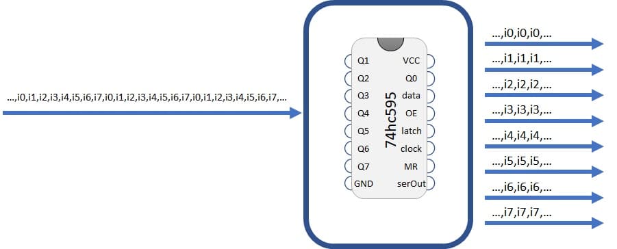
The shift register chip is an electronic element able to acquire a serial data flow from one of its PINs (data PIN), store these data and expose them in its 8 output PINs (Q0, Q1, …Q7).
Each output pin can have 0 (off) or 1 (on) value. To set each of these values on or off, we feed in the data using the data and clock PINs of the chip in a precise timing diagram. The clock needs to receive nine pulses. At each pulse (on rising edge), if the data PIN is high then a 1 gets pushed into the shift register; otherwise, a 0.
When all eight pulses have been received, enabling the ‘latch’ pin stores those eight values to register and exposes them in output PINs:
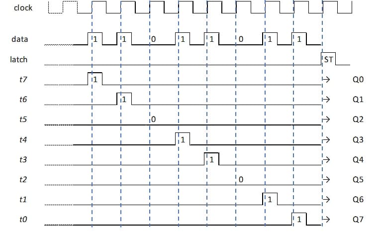
As you can see in this picture, it is important that your data to transfer is stable before rising edge of clock signal because this is the moment when transfer is done.
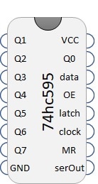
Beside output PINS (Q0…Q7), data, clock and latch, other PINS are exposed from 74hc595:
- Vcc and GND: of course, 5v and ground to power output
- OE (Output Enable): This PIN enables or disables output. 74hc595 exposes output when OE is low (0)
- MR (Master Reclear): This PIN cleans memory when put to 0. So, having 74hc595 working means MR connected to 1.
- serOut (Serial Output): is used when you need to drive a second shift register attached to this one.
What We Need
As usual, I suggest adding from now to your favourite e-commerce shopping cart all the needed hardware, so that at the end you will be able to evaluate overall costs and decide if to continue with the project or remove them from the shopping cart. So, hardware will be only:
- Raspberry PI Zero W (including proper power supply or using a smartphone micro usb charger with at least 3A) or newer Raspberry PI Board
- high speed micro SD card (at least 16 GB, at least class 10)
- Dupont Wiring
- Solderless breadboard
- Resistors
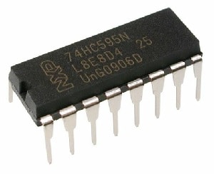
- 74HC9595 chip
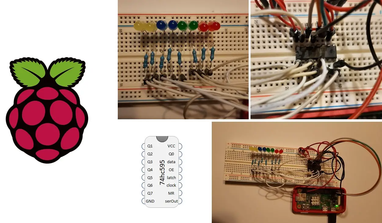
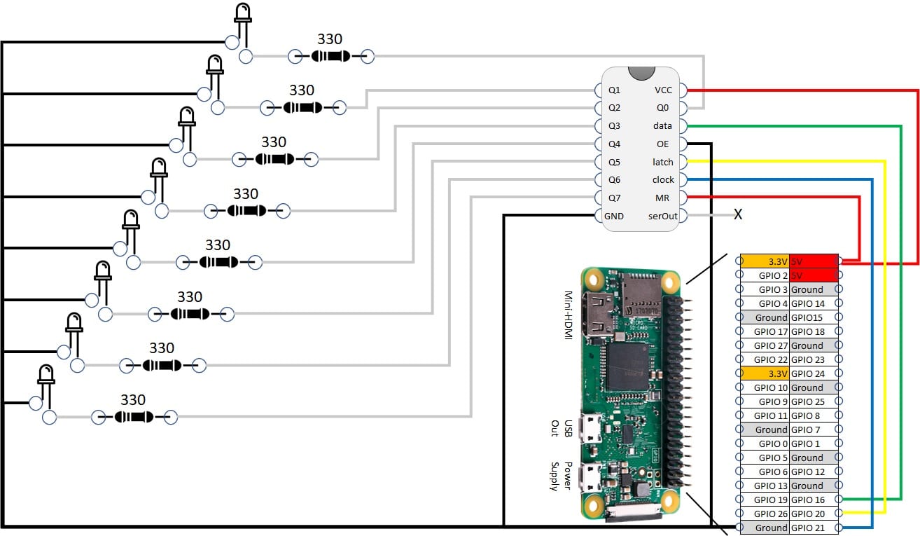
Wiring Diagram
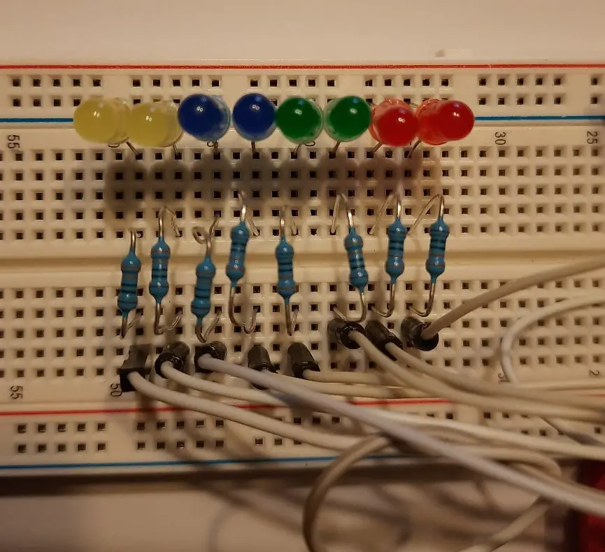
Please find in following picture the wiring diagram for this project. Note that LED longer PIN (positive) goes toward Shift Register. SerOUT remains unconnected.
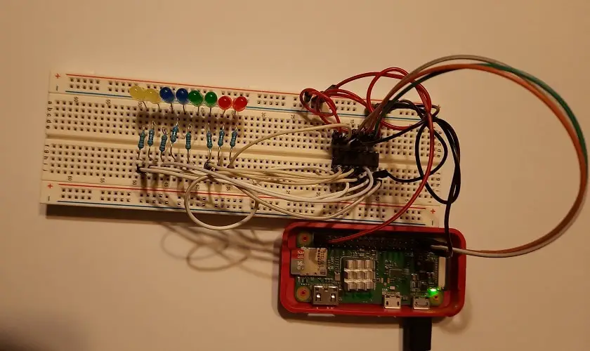
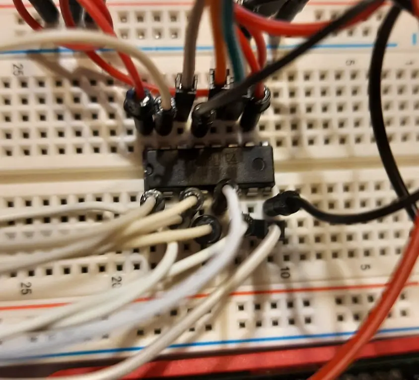
Please find below some pictures with details:
Step-by-step Procedure
Prepare Operating System
Start preparing your PI installing Raspberry PI OS Lite. This tutorial applies also to Raspberry PI OS Desktop, by using its internal terminal.
Make your OS up to date. From terminal:
sudo apt update -y && sudo apt upgrade -yRPI.GPIO should be already installed (otherwise, you can get it installed with the command “sudo apt install python3-rpi.gpio”).
Import Python Script
You can get my shift_register.py python script directly in your RPI from terminal:
wget https://peppe8o.com/download/python/shift_register.pyCode is explained in following paragraph.
Required packages are imported:
import RPi.GPIO as GPIO
import sys
Then PIN are assigned to variables for better management. These values match showed wiring diagram. If you used other PINs, please edit according to Raspberry PI BCM pinout according to your cabling:
dataPIN = 16
latchPIN = 20
clockPIN = 21
PIN are thes set to output:
GPIO.setmode(GPIO.BCM)
GPIO.setup((dataPIN,latchPIN,clockPIN),GPIO.OUT)
A function is used to manage shift register update call. This function requires 4 parameters:
- input -> a string containing 8 chars composed only of “1” and “0”
- data -> to identify data transmission PIN
- clock -> to identify clock signal PIN
- latch -> to identify latch PIN
This function also manages clock signal before and after each step:
- latch to zero,
- data transmission
- latch to 1
Data is transmitted in reverse order because Q7 output must enter the data port first, followed by other data according to timing diagram.
def shift_update(input,data,clock,latch):
  #put latch down to start data sending
  GPIO.output(clock,0)
  GPIO.output(latch,0)
  GPIO.output(clock,1)

  #load data in reverse order
  for i in range(7, -1, -1):
    GPIO.output(clock,0)
    GPIO.output(data, int(input[i]))
    GPIO.output(clock,1)

  #put latch up to store data on register
  GPIO.output(clock,0)
  GPIO.output(latch,1)
  GPIO.output(clock,1)
With this function available, using it inside our main script requires simply:
shift_update(sys.argv[1],dataPIN,clockPIN,latchPIN)The “sys.argv[1]” is used to pass our byte directly as argument on script execution. Infact, sys.argv[] system property allows passing arguments from terminal to script with an array ordered as following:
$ python test.py       arg1         arg2         arg3       ...
           |            |            |            |
       sys.argv[0]  sys.argv[1]  sys.argv[2]  sys.argv[3]   ...
with sys.argv[0] returning “test.py”, sys.argv[1] returning “arg1” and so on.
Final operation cleans GPIO PINs status, while last update remains stored on Shift Register:
GPIO.cleanup()Run the Script
Running our script requires a simple terminal command:
python3 shift_register.py 00000000changing the string of 8 zeroes with “1” or “0” according to your need.
Some examples:
python3 shift_register.py 10101010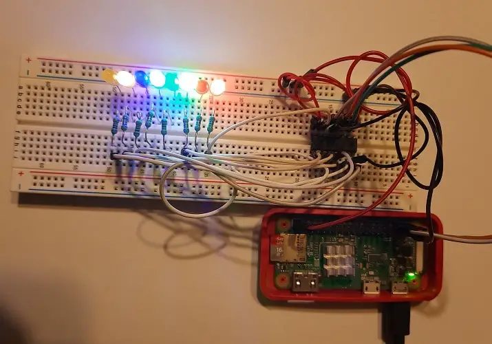
One more example:
python3 shift_register.py 11100011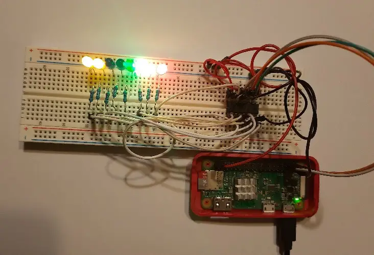
Last example:
python3 shift_register.py 00000011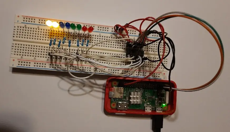
Enjoy!

Open source and Raspberry PI lover, writes tutorials for beginners since 2019. He's an ICT expert, with a strong experience in supporting medium to big companies and public administrations to manage their ICT infrastructures. He's supporting the Italian public administration in digital transformation projects.
![]()
![]()
![]()
![]()
![]()
![]()
![]()


Excellent, thank you !. I can understand now this shift register.
Do you know a similar post about SN74LS165 parallel to serial SR ?
Hi Jean.
Thank you for your feedback. Honestly, I’ve never get a SN74LS165. From what I googled, this is a parallel to serial device and could make sense only as input for Raspberry PI (as for output the RPI is already capable to transmit in serial). So, something similar to the current code should applg also for these chips