
Last Updated on 13th April 2024 by peppe8o
In this tutorial, the I2C based protocol OLED interface with Arduino Uno includes code, a connection diagram, and a component list.
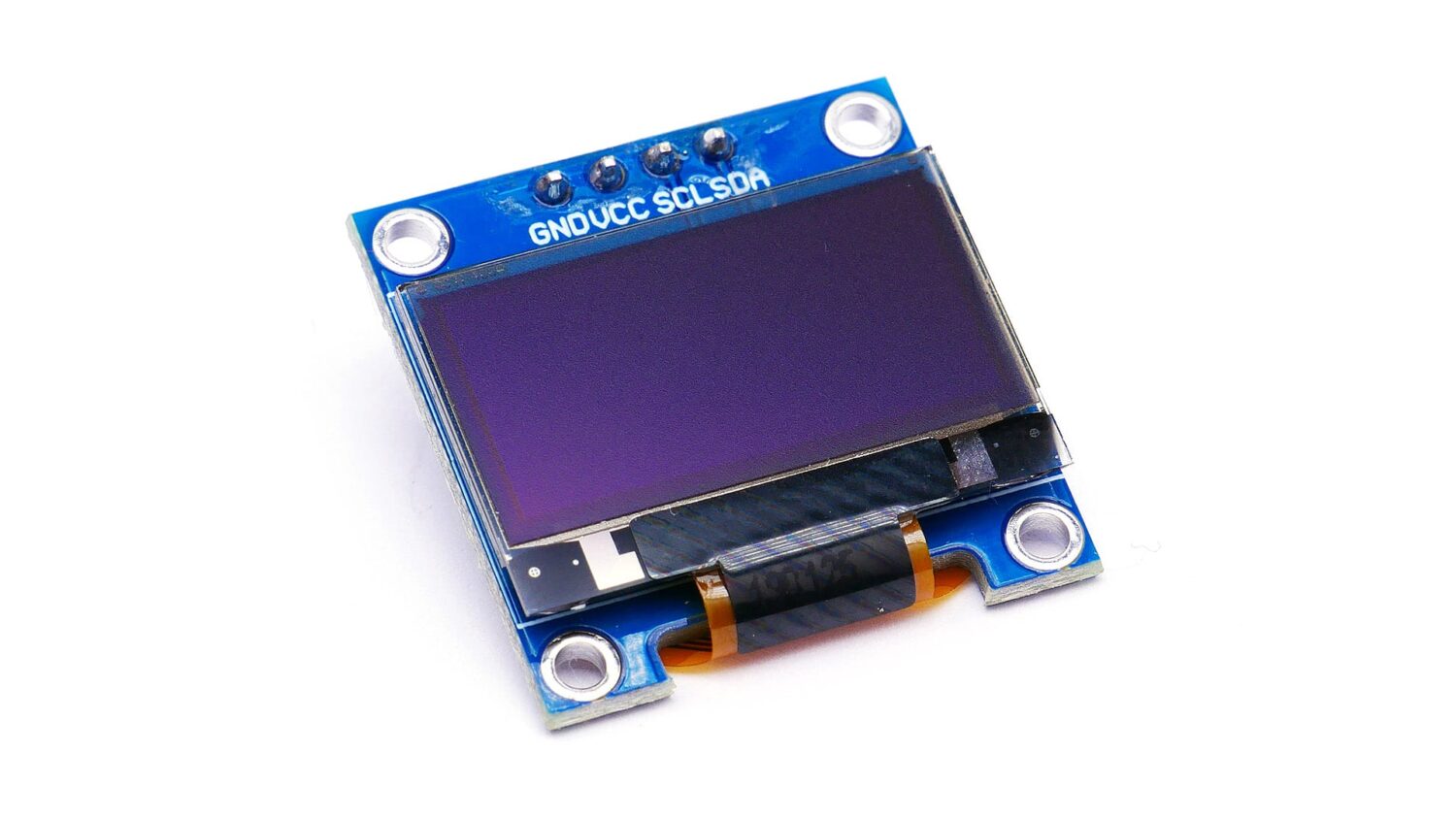
To see the data on the screen which good pixels display OLED is best to choose, it comes in two pixels 128 X 64 and 128 X 32 both have efficient results
How OLED Works
OLED is a solid-state semiconductor technology made up of thin films of organic molecules that emit light when electricity apply. The OLED emitter is the most important part of an OLED display; An OLED’s basic structure is an emissive layer sandwich between a cathode ( electrons emitter) and an anode (electron receiver).
- OLED is very thin in size and lighter in weight than other displaying components;
- It has a wide field of view (up to 160 degrees even in bright light);
- This display consumes less power than traditional LED and LCD displays;
- It has a colourful display with an attractive look to please the eyes and make it user-friendly.
Working Principle of OLED
When you apply a voltage to OLED, each of the two electrodes, which have a positive and negative electric charge, generates holes and electrons. Organic molecules cause the emissive layer to transform into a high-energy state known as “excitation” when they recombine in the emissive layer. When the layer regains its previous stability, light emits.
Comparison of OLED with other displays
- OLEDs have plastic, organic layers that are thinner, lighter, and more flexible than crystalline layers found in LEDs and LCDs.
- Because the organic layers are thinner, the display is brighter than LEDs.
LCDs do not require backlighting. - Much less power consumption, which is significant for battery-operated devices.
- OLEDs are easy to make on a larger scale.
- It has a viewing angle of 160 degrees.
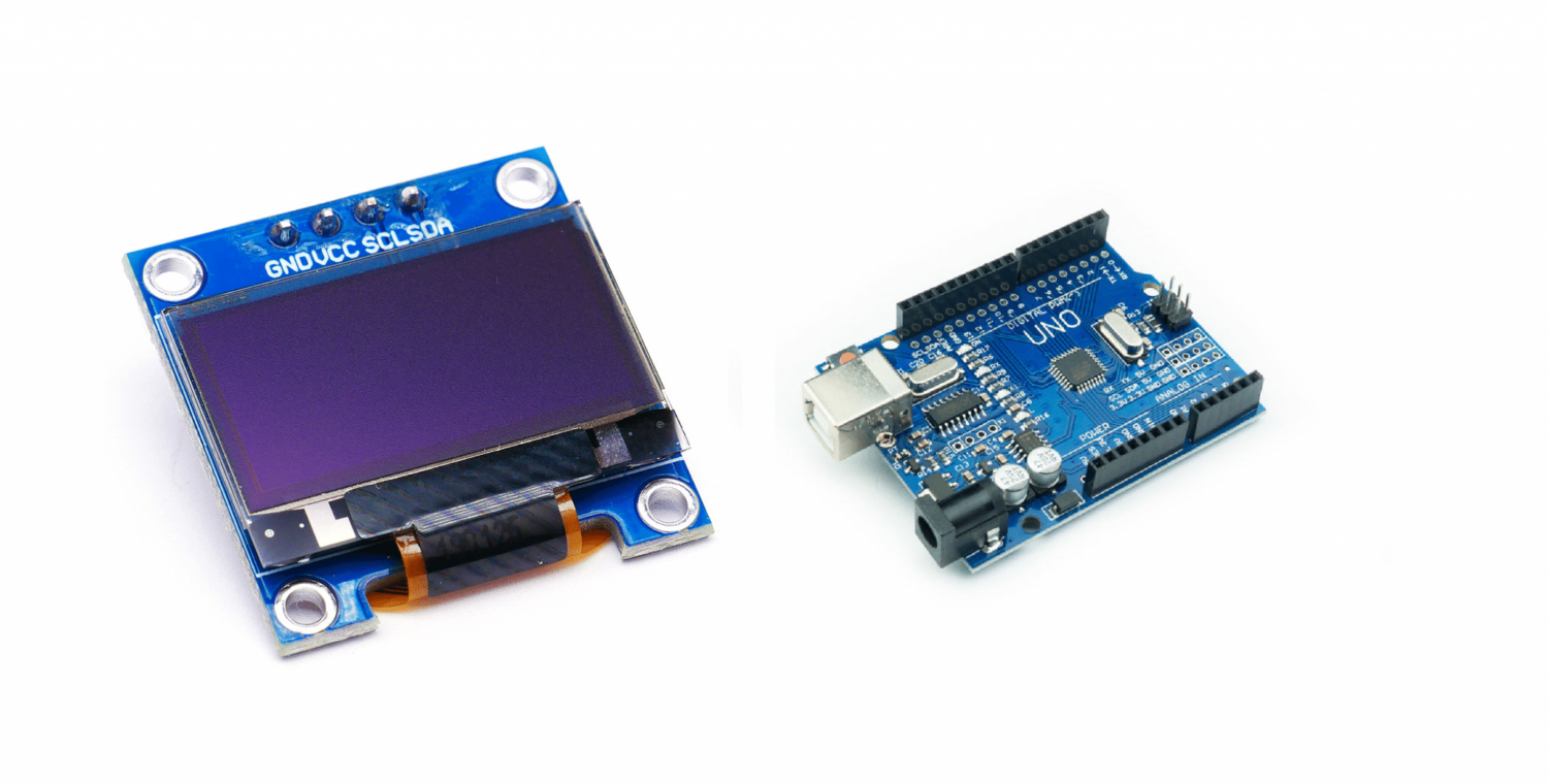
What We Need?
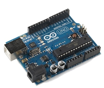
As usual, I suggest adding from now to your favourite e-commerce shopping cart all the needed hardware, so that at the end you will be able to evaluate overall costs and decide if to continue with the project or remove them from the shopping cart. So, hardware will be only:
Check hardware prices with the following links:

Step-by-Step Procedure
Wiring Diagram of OLED with Arduino
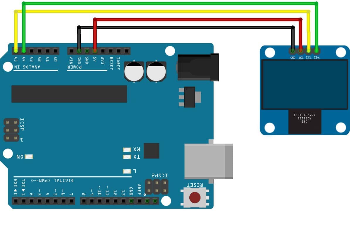
As shown in the image below, the module connects with Arduino Uno. Please follow the wiring that presents in the picture, Tutorial on to Arduino Uno Pinout follow to make the connections.
| Sr. | OLED pin name | Arduino pin name |
| 1 | GND | GND |
| 2 | VCC | 5V |
| 3 | SCL | A5 |
| 4 | SDA | A4 |
Get OLED.ino, library and Code Explanation
Connect your PC to Arduino and open Arduino IDE. For the very first steps, you can refer to Connecting Windows PC with Arduino tutorial. You can get the .ino code and libraries from my download area with the following link:
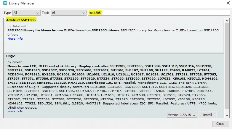
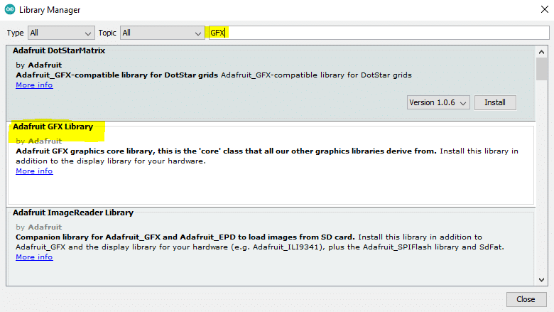
You also need to install the following library, according to my Install Arduino Libraries: methods to add libraries with Arduino IDE tutorial. Please get the zip files from following links or add it from available libraries in your Arduino IDE:
adafruit-gfx-library-master.zip
From Arduino IDE library manager, you can find both libraries by using the search field:
This OLED works on the I2C protocol, so the I2C library includes related pins that are defined. In Arduino Uno, I2C pins are A4 and A5.
Section 1: Before Setup, the Library for I2C uses to initialize the I2C communication. Then GFX graphic and driver of SSD1306 library includes. Pixel of OLED is set to 128 X 64, while some OLED contains reset so it includes. In our case, we don’t need the reset pin. The I2C address of the OLED is provided for communication.
#include <Wire.h>
#include <Adafruit_GFX.h>
#include <Adafruit_SSD1306.h>
#define SCREEN_WIDTH 128 // OLED display width, in pixels
#define SCREEN_HEIGHT 64 // OLED display height, in pixels
#define OLED_RESET     4 // Reset pin # (or -1 if sharing Arduino reset pin)
#define SCREEN_ADDRESS 0x3D //< See datasheet for Address; 0x3D for 128x64, 0x3C for 128x32
Adafruit_SSD1306 display(SCREEN_WIDTH, SCREEN_HEIGHT, &Wire, OLED_RESET);
Section 2: Setup Section
The serial monitor initializes at a 9600 baud rate. And OLED is initialized if case it failed to communicate code will be stuck over that line. The function display.display () uses to display the data on the screen. The data is already sent to the OLED through the command of display.drawPixel, display.invertDisplay. All the commands execute in visualization when display.display command is sent. In short words, data remain stored in the register of the OLED until display.display is sent to perform the action.
void setup() {
  Serial.begin(9600);
  // SSD1306_SWITCHCAPVCC = generate display voltage from 3.3V internally
  if (!display.begin(SSD1306_SWITCHCAPVCC, SCREEN_ADDRESS)) {
    Serial.println(F("OLED not Found, Check Connections"));
    for (;;); // Don't proceed, loop forever
  }
  display.display();
  delay(2000); // Pause for 2 seconds

  display.clearDisplay();
  display.drawPixel(10, 10, SSD1306_WHITE);   // Draw a single pixel in white
  display.display();
  delay(2000);
  display.invertDisplay(true);                // Invert and restore display, pausing in-between
  delay(1000);
  display.invertDisplay(false);
  delay(1000);
}
Section 3: Loop
In this section, a continuous routine is performed, display.clearDisplay() clear the screen data. display.setTextSize(2), this is used to change the font size of the text, these come in integer float values are not allow, 1,2,3,4. Display.textcolor controls the text colour, there are 128X64 pixels in the OLED. so we can set the scroll at a maximum of (128,64). display.println uses to display the string. display,display prints the data to the screen.
void loop()
{
  display.clearDisplay();
  display.setTextSize(2); // Draw 2X-scale text
  display.setTextColor(SSD1306_WHITE);
  display.setCursor(10, 0);
  display.println(F("Mytest"));
  display.display();      // Show initial text
  delay(1000);
}
What’s Next
Please find more tutorials on Arduino in peppe8o Arduino archives.
Enjoy!
Umar Jamil
For any queries and help for work, please contact me at:
Whatsapp: +92-346-661-7017
Email: umarjamil0007@gmail.com

I'm an Electronic Engineer, well-skilled to solve the issues of hardware and software. I do have laboratory which contains unlimited sensors and modules for testing the working. Also, I am experienced in Arduino programming, Android mobile application, microcontroller programming, IOTs and embedded projects. I provide services to control, realize the sensor data in the Mobile Application. For any queries and help for work Contact: Whatsapp:+92-346-661-7017 Email: umarjamil0007@gmail.com
![]()


