Last Updated on 13th April 2024 by peppe8o
In this tutorial, I’m going to show you how to create a smart farm architecture by using a Raspberry PI computer board as a central processing and data presentation, while a Raspberry PI Pico microcontroller with WIZnet Ethernet HAT will collect data from your farm.
IoT devices have wide industry application fields. But they can also help improve some sectors such as agriculture to better use resources and keep under control your production
Please note that the steps covered in this tutorial should also work with the W5100S-EVB-Pico board.
NOTE: this article has been appointed as “Honorable Mention” in WIZnet Ethernet HAT Contest 2022.
The Goal
High-density farming usually consumes a lot of resources as some maintenance and growth tasks are based on time-frequency instead of real plant needs. Moreover, adverse weather conditions (like temperature too low or humidity out of supported values) can cause damage to crops if not managed in time. All of these tasks are even harder to keep under control in the case of big areas.
Having a monitoring automation system can help farmers, warning them when pre-fixed conditions are in progress. With a bit more integration, some electronic controls can also be activated, so also automating countermeasures to get your crops safe.
Moreover, by integrating controls to activate/deactivate external devices like, for example, electrical water valves, you can set farm maintenance to work when and only when it is required (and not simply based on timing). Still, about watering example, you can think of your farm divided into sectors each one controlled by a Raspberry PI Pico / WIZnet Ethernet HAT, DHT11 sensor and soil moisture sensor. Each sector will enable its watering valve only when the soil moisture goes below a specified threshold value. The watering task can be less than the common manual watering time: this will allow a lower water dispersion and the required moisture percentage will be satisfied from a more frequent watering as everything will be automated. Less water dispersion means fewer world resources usage and a more green world.
This project aims to create a fully open source and fully customizable solution which uses an IoT architecture to collect data from the field and send them to a low-cost, centralized server (it can be a Raspberry PI computer board like Raspberry PI 3/4 Model B).
Data will be sent via MTTQ messages and organized into powerful dashboards with Thingsboard, which can set warnings and activate related tasks.
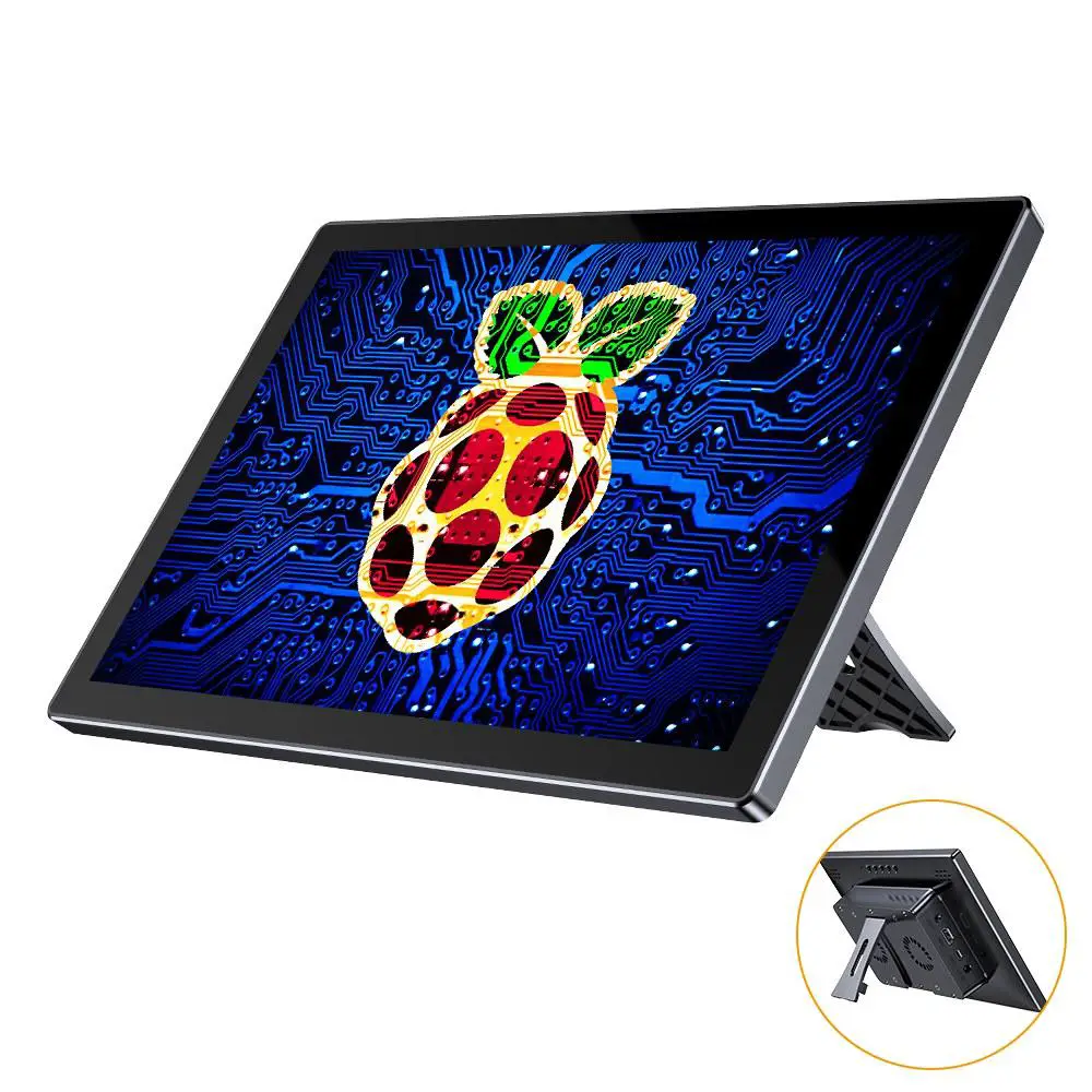
Within this project, I’ll use a Uperfect touchscreen display to show our Smart Farm dashboard. Even if not strictly required, this display is a great solution for a wall mount as its backpack can host a Raspberry PI Model B and it already has holes to install on a wall in a kiosk-like configuration. But you can also use only the Raspberry PI alone and see the resulting dashboard from a remote device with a common browser (like a smartphone, tablet or PC).
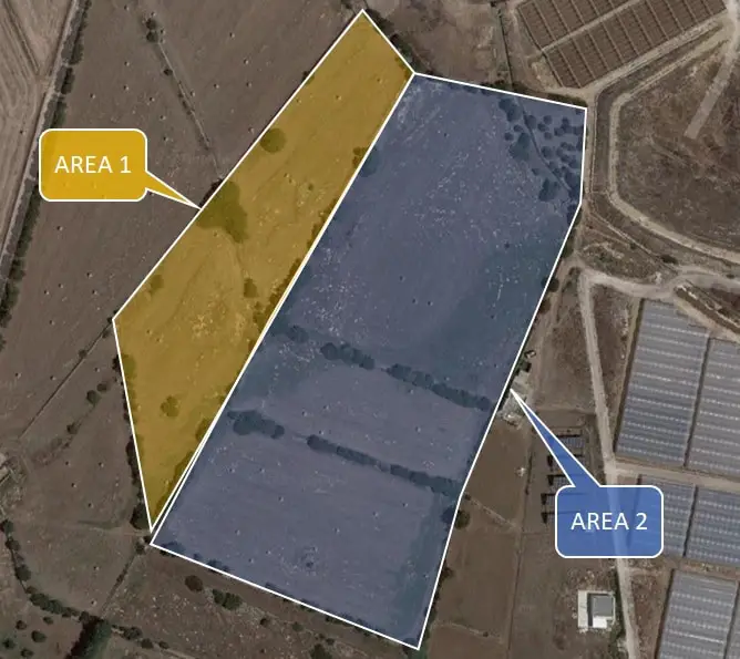
I’ll assume we are going to manage a farm divided into 2 main areas (maybe, for example, corn in one area and vegetables in the second one). A picture of this hypothetic farm can be the following:
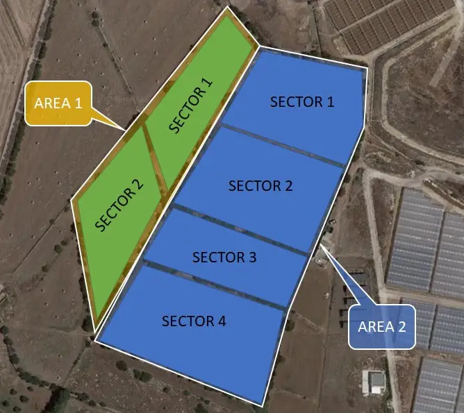
Each area will be divided into a number of sectors, each one representing a measurement sample. The following picture shows sectors inside the areas:
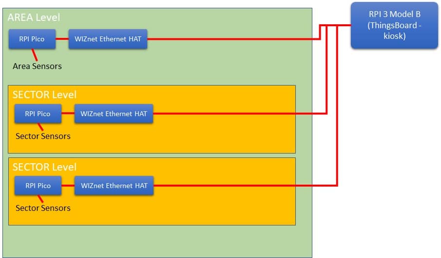
The following picture shows the general architecture for this project. Raspberry PI Pico and WIZnet Ethernet HAT will collect sensor data from Areas and Sectors, transmitting them to the main mind of the project: a Raspberry PI 3 Model B (or newer) computer board hosting ThingsBoard. This RPI can also be set to show dashboards with a touchscreen display (I will show you the Uperfect display, as it natively integrates a backpack for Raspberry PI computers). You can replicate this architecture for as many sectors as you need. The project modularity will allow you to reuse code and adapt it easily to your sensors. The sector level can also control small devices such as solenoid valves to activate watering in specified conditions.
What We Need
As usual, I suggest adding from now to your favourite e-commerce shopping cart all the needed hardware, so that at the end you will be able to evaluate overall costs and decide if to continue with the project or remove them from the shopping cart. So, hardware will be only:
- Raspberry PI 3 Model B+ (including proper power supply or using a smartphone micro usb charger with at least 3A)
- high speed micro SD card (at least 16 GB, at least class 10)
- a USB/wireless keyboard
- Raspberry PI Pico microcontroller (with a common micro USB cable)
- a WIZnet Ethernet HAT (you can check it from Mouser or from Digikey)
- breadboard (for prototype)
- dupont wirings (for prototype)
- Uperfect RPI All-In-One monitor
- DHT11 sensor module
- any other sensor needed for your farm
Step-by-Step Procedure
Install Raspberry PI Computer OS
Start installing the Raspberry PI OS on your RPI computer board (Raspberry PI 3 Model B/B+ or Raspberry PI 4 Model B).
If you are going to use it as a stand-alone server, you can install Raspberry PI OS Lite and then move to the “Install ThingsBoard” chapter. in this way, you’ll be able to access your dashboard from any device with a browser running on the same network as the Raspberry PI computer or able to reach it (with a VPN or by exposing Thingsboard to the internet after securing this.
On the other hand, if you want to use a touchscreen with your RPI computer, you have to install Raspberry PI OS Desktop. Please, mind enabling SSH remote access as explained in the referred tutorial. This way you’ll be able to use ThingsBoard from preferred your remote device, but you will also be able to keep a monitor showing the dashboard (for example with a wall mount).
Add Uperfect Touchscreen (optional)
Adding a Uperfect touchscreen is a very simple task, as the producer already gives a very good tutorial, I’ve reviewed this device in my Raspberry PI Touchscreen: reviewing the Uperfect RPI All-In-One article. Moreover, as an additional tip, you can also use my Raspberry PI Kiosk: create a touchscreen, informative stand to make the dashboard appear (with a fullscreen) at its boot.
Install Thingsboard on Raspberry PI
Now, it’s time to install ThingsBoard. Also here, all the required steps and tricks to improve performances have been detailed in my ThingsBoard and Raspberry PI (part 1): getting a Professional IoT dashboard tutorial. Basically, the main operations here are:
- Install Java
- Download ThingsBoard deb package
- install ThingsBoard
- Install Postgres database
- Configure a new database for ThingsBoard
- Prepare ThingsBoard configuration file
- Initialize and run ThingsBoard
Configure the new Thingsboard Tenant
With ThingsBoard installed, you have to create your first tenant from the System Administrator console. Also, this part is detailed in my second tutorial on ThingsBard: ThingsBoard and Raspberry PI (part 2): Add Device telemetry by MTTQ and Python.
Think of the tenant as a space collecting all the projects having a common customer. You can create as many tenants as you want, but if this project will serve only your spaces, then one single tenant will be enough.
So, the operations are the following:
- From the System Admin dashboard, create a new tenant
- With the created tenant, create a tenant Admin and activate it (during the tenant activation stage, an activation link will be provided). From here, you can logout the System Admin and continue on Tenant Admin console
- Create a new Device
During the device creation, I suggest thinking of using a naming convention for devices able to keep you aware of what the device represents. For example, a naming like Pico#1, Pico#2, and so on will be enough for the prototyping stage, but it will be hard to manage in production, where something like “Area xx, Sector yy” could be far better. Anyway, you can modify the device label during usage.
When you create the new device, please note that with Raspberry PI Pico and WIZnet Ethernet HAT you have to set the Device Credentials to MQTT Basic. This will be something similar to the following picture:
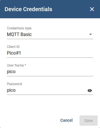
Of course, please set your User Name and password according to your preferences.
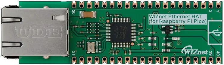
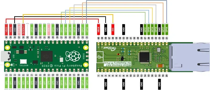
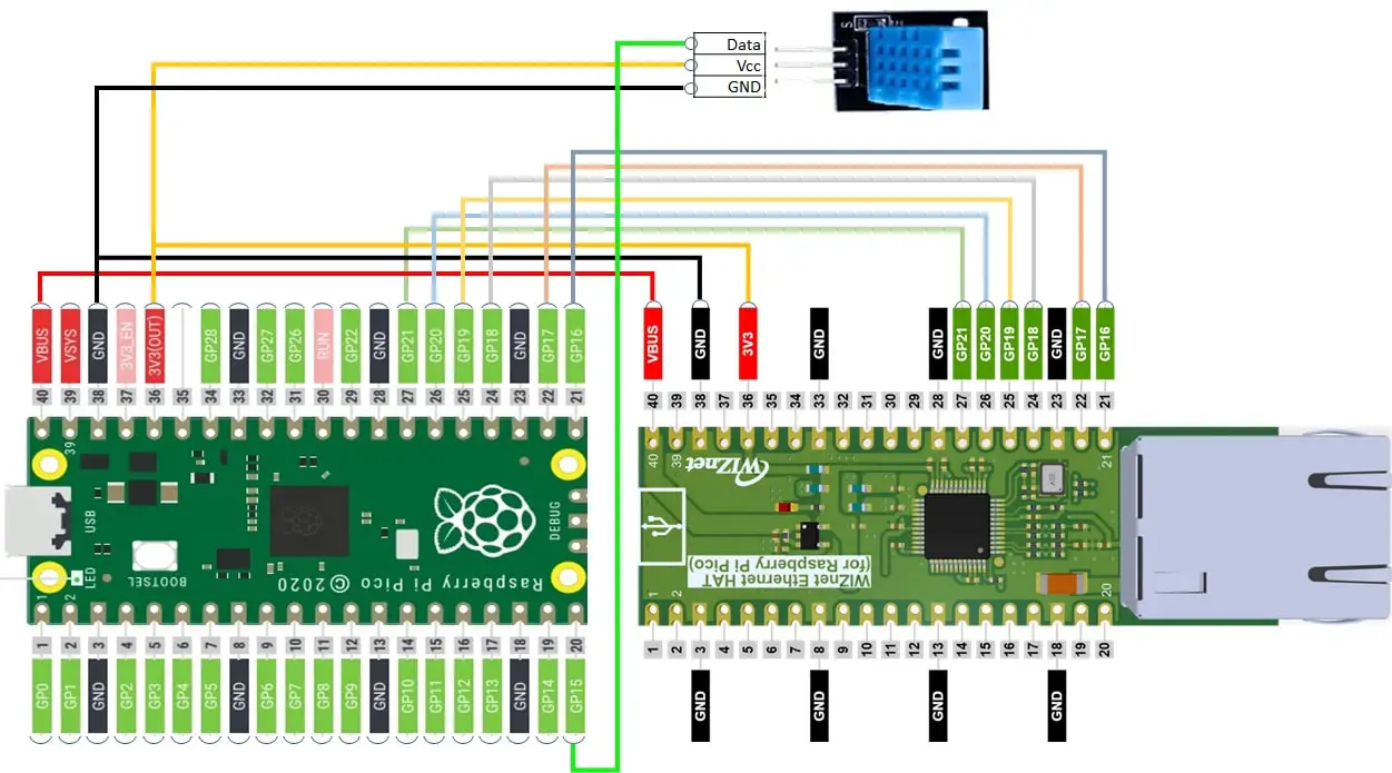
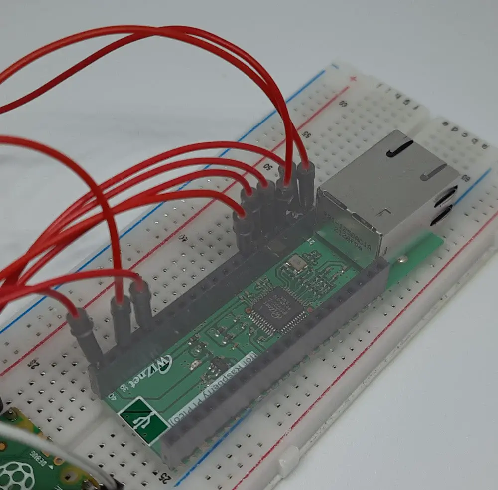
Wiring the Raspberry PI Pico and WIZnet Ethernet HAT
For the prototype, you can get help from a breadboard for cabling. The WIZnet Ethernet HAT uses GP from 16 to 21 to communicate with Raspberry PI Pico, besides the Power/ground connection (a great improvement for the future of this HAT can be getting Power Over Ethernet, so becoming the power source for the Pico). Cabling must be set according to the following picture:
Setup the MicroPython code (and test)
Install the Raspberry PI Pico MicroPython firmware. At the time of this post, I suggest using the one from the WIZnet page on GitHub or you can download it by using my download area link -> firmware.uf2). To install it, you can also refer to my W5100S-EVB-Pico: A Raspberry PI Pico with Ethernet port tutorial, as using the W5100S-EVB-Pico or the WIZnet Ehetnet HAT is the same.
Once installed the firmware, get the following two files from the WIZnet libraries page on GitHub or getting them from my download area:
Copy these files in your Raspberry PI Pico root folder or inside a “lib” folder (as explained in my Adding external modules to MicroPython with Raspberry PI Pico).
Create a new “main.py” file in your Raspberry PI Pico root folder and add the following code:
from umqttsimple import MQTTClient
import time
import ubinascii
from machine import Pin,SPI
from usocket import socket
import network
import rp2

#mqtt config
mqtt_server = '192.168.1.91'
client_id = 'Pico#1'
user_t = 'pico'
password_t = 'pico'
topic_pub = 'v1/devices/me/telemetry'

last_message = 0
message_interval = 5
counter = 0

#W5x00 chip init
def w5x00_init():
    spi=SPI(0,2_000_000, mosi=Pin(19),miso=Pin(16),sck=Pin(18))
    nic = network.WIZNET5K(spi,Pin(17),Pin(20)) #spi,cs,reset pin
    nic.ifconfig(('192.168.1.20','255.255.255.0','192.168.1.1','8.8.8.8'))
    while not nic.isconnected():
        time.sleep(1)
        print(nic.regs())

#MQTT connect
def mqtt_connect():
    client = MQTTClient(client_id, mqtt_server, user=user_t, password=password_t, keepalive=60)
    client.connect()
    print('Connected to %s MQTT Broker'%(mqtt_server))
    return client

#reconnect & reset
def reconnect():
    print('Failed to connected to MQTT Broker. Reconnecting...')
    time.sleep(5)
    machine.reset()

def main():
    w5x00_init()
    try:
        client = mqtt_connect()
    except OSError as e:
        reconnect()

    while True:
        try:
            client.publish(topic_pub, msg='{"Temperature":19.6}')
            client.publish(topic_pub, msg='{"Humidity":53.0}')
            print('published')
            time.sleep(3)
        except:
            reconnect()
            pass
    client.disconnect()

if __name__ == "__main__":
    main()
Please change the following parts according to your installation:
mqtt_server = ‘192.168.1.91’ -> Raspberry PI (ThingBoard) server IP address
client_id = ‘Pico#1’ -> MTTQ credentials set on ThingsBoard
user_t = ‘pico’ -> MTTQ credentials set on ThingsBoard
password_t = ‘pico’ -> MTTQ credentials set on ThingsBoard
nic.ifconfig((‘192.168.1.20′,’255.255.255.0′,’192.168.1.1′,’8.8.8.8’)) -> Your Network configuration for your Raspberry PI Pico
This configuration will start sending MTTQ messages to your ThingsBoard. For this test, we’re sending static messages for “Temperature” and “Humidity” variables, set respectively to 19.6 and 53.0. You can edit these messages at your choice, also depending on your sensors, as we’ll see in the next paragraph. The format has to be “telemetry_name: televetry_value”. Please note that you are free to choose whatever name you want to give to your telemetry variable.
Also, note the sleep(3) line. It adds 3 seconds delay on each measurement. As your devices increase in number, it is a good practice to reduce the number of messages sent to the Raspberry PI server in order to keep good performances and avoid overload.
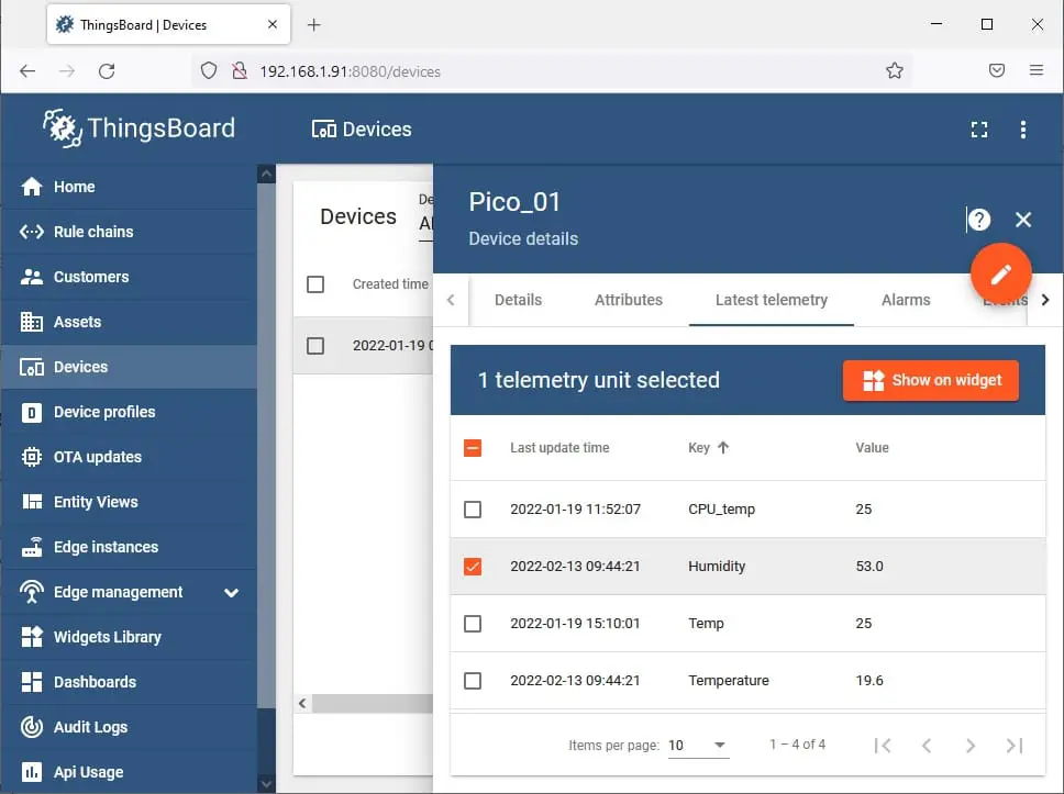
To check that the communication worked properly, in your ThingsBoard Dashboard (as Tenant Admin) go to Devices, click on your Raspberry PI Pico entry and select the “Latest Telemetry” tab. You should see something like the following:
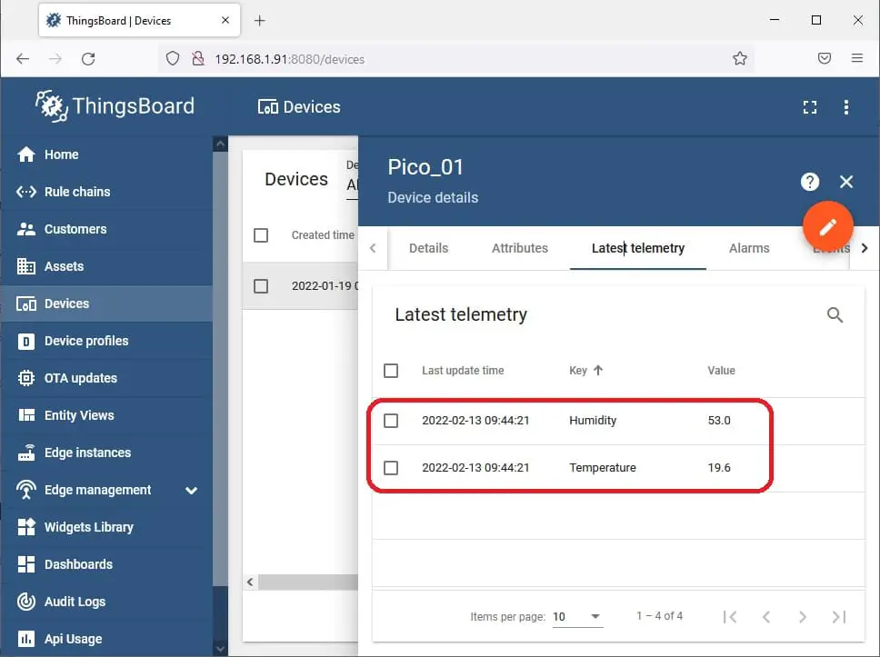
If so, your Raspberry PI Pico is correctly connecting, authenticating and sending messages and you can proceed with the next step.
Add Sensors
For this tutorial, we’re going to add a DHT11 temperature and humidity sensor. It is a cheap sensor giving good temperature and humidity measurements for farming purposes. It requires 3,3V power, besides a GND connection, and a data PIN. The wiring can be arranged according to the following diagram:
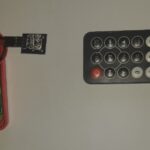
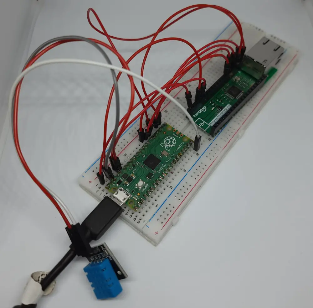
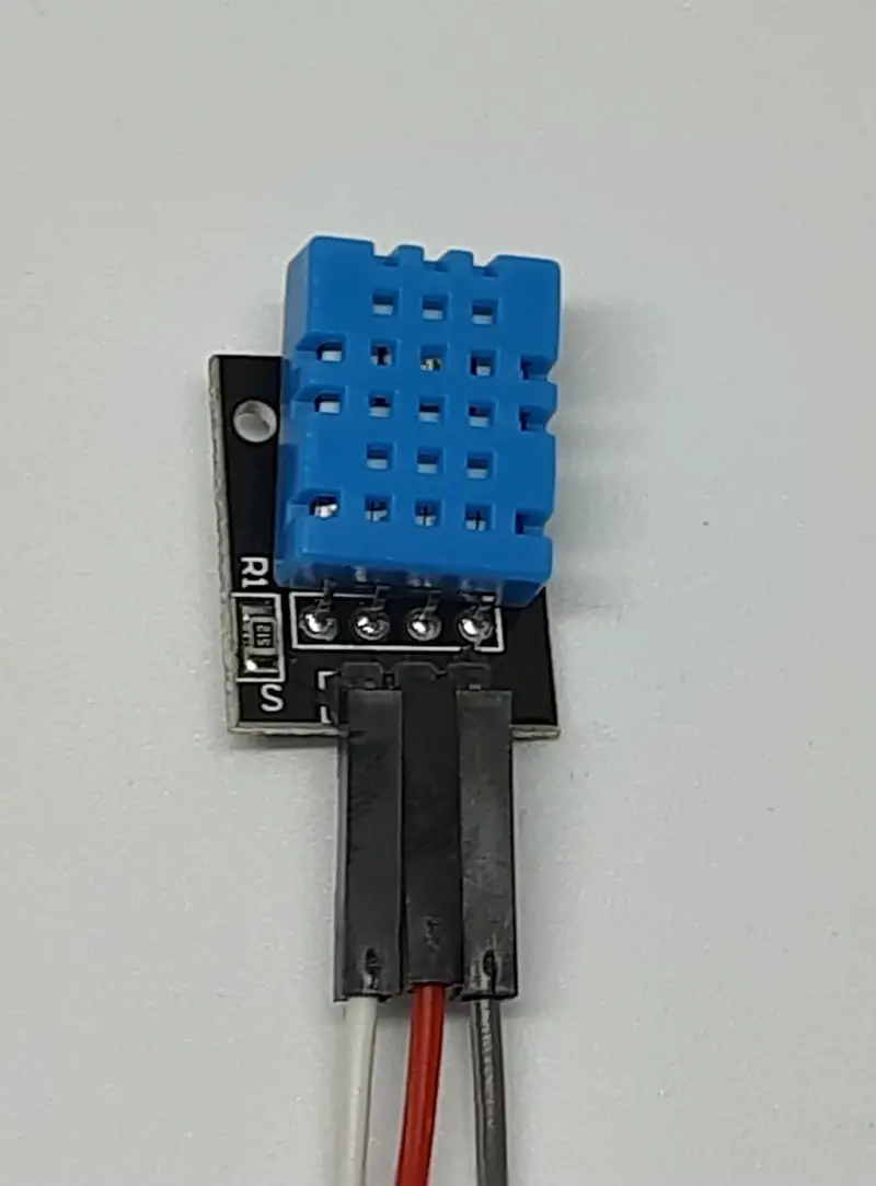
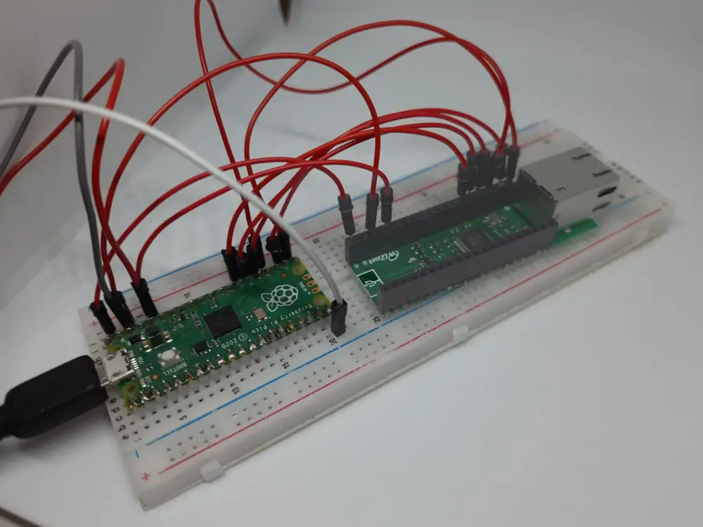
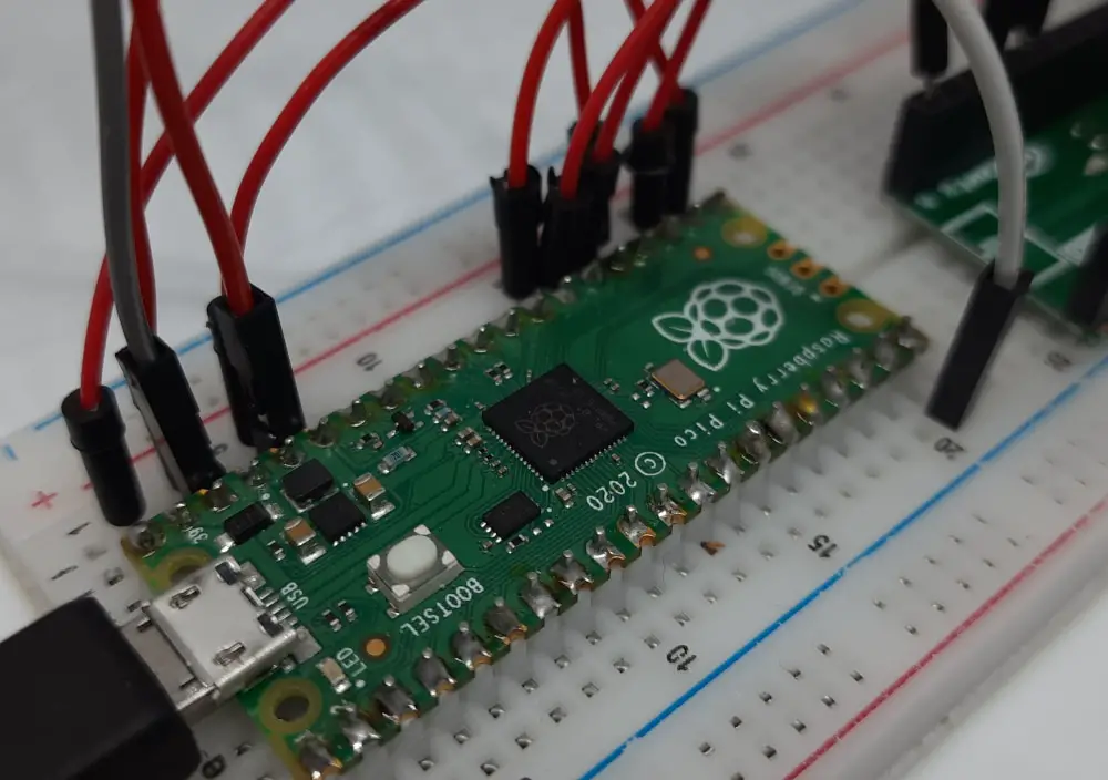
Please find below some pictures from my lab:
Download the “dht.py” file from GitHub repository of ikornaselur.
You can also download a copy of it from my download area with the following link:
Add this file to your Raspberry PI Pico library path (so, in the root folder or in your lib folder). We can now modify the main.py code in our Raspberry PI Pico with the following (changes compared to the previous file are highlighted in red, but remember to keep the same IP/authentication settings from the previous stage):
from umqttsimple import MQTTClient
import time
import ubinascii
from machine import Pin,SPI
from usocket import socket
import network
import rp2
from dht import DHT11, InvalidChecksum

#dht11 config
dhtPIN = 15
dhtSensor = DHT11(Pin(dhtPIN, Pin.OUT, Pin.PULL_DOWN))

#mqtt config
mqtt_server = '192.168.1.91'
client_id = 'Pico#1'
user_t = 'pico'
password_t = 'pico'
topic_pub = 'v1/devices/me/telemetry'

last_message = 0
message_interval = 5
counter = 0

#W5x00 chip init
def w5x00_init():
    spi=SPI(0,2_000_000, mosi=Pin(19),miso=Pin(16),sck=Pin(18))
    nic = network.WIZNET5K(spi,Pin(17),Pin(20)) #spi,cs,reset pin
    nic.ifconfig(('192.168.1.20','255.255.255.0','192.168.1.1','8.8.8.8'))
    while not nic.isconnected():
        time.sleep(1)
        print(nic.regs())

#MQTT connect
def mqtt_connect():
    client = MQTTClient(client_id, mqtt_server, user=user_t, password=password_t, keepalive=60)
    client.connect()
    print('Connected to %s MQTT Broker'%(mqtt_server))
    return client

#reconnect & reset
def reconnect():
    print('Failed to connected to MQTT Broker. Reconnecting...')
    time.sleep(5)
    machine.reset()

def main():
    w5x00_init()
    try:
        client = mqtt_connect()
    except OSError as e:
        reconnect()

    while True:
        try:
            dht_temp=dhtSensor.temperature
            dht_hum=dhtSensor.humidity
            client.publish(topic_pub, msg='{"Temperature":'+str(dht_temp)+'}')
            client.publish(topic_pub, msg='{"Humidity":'+str(dht_hum)+'}')
            print('published')
            time.sleep(3)
        except:
            reconnect()
            pass
    client.disconnect()

if __name__ == "__main__":
    main()
This version adds the DHT11 measure checks, associate them with variables and adds them to the MTTQ message. Please note that the str() function converts numbers to strings in order to ship the message correctly.
The same logic can be applied to whatever sensor you need (for example, a capacitive soil moisture sensor controlled by Raspberry PI Pico). Get the sensor libraries (if needed) for MicroPython, create a variable that stores the value and send the MTTQ message with the telemetry name and value. These values will be shown in your ThingsBoard telemetry, updated in real-time with the latest value.
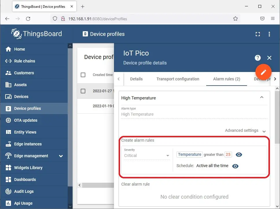
Adding Alarms and Trigger
Alarms can be managed at the ThingsBoard level with Device profiles. Think of a device profile as something that makes it possible for you to set when the device creates a state which can generate a trigger to perform an action. This doesn’t mean that we are creating the action, here we’re defining the conditions. For example, you can create a new IoT Pico profile that generates a critical alarm when the temperature exceeds 25 degrees, getting a device profile like the following:
You can then associate your Raspberry PI Pico to this profile so that it will create this alarm every time the temperature measured from the device exceeds this threshold. Please note that this alarm is generated at ThingsBoard level, so the RPI Pico won’t be aware of the alarm. When you create a new device profile and you want to apply it to an existing device, please remember to edit the device and associate it to the new profile.
Triggers, on the other hand, can be set both at Raspberry PI Pico level and ThingsBoard level. Triggers at the ThingsBoard level are those needing high-level management: sending a warning email/SMS, activating a water pump or a conditioning system could need a higher logic not available at the RPI Pico level. These actions will be managed from ThingsBoard with the Rule Chains (for this topic, please refer ThingsBoard Rule Chains docs). Again, when a new rule chain is created, remember to associate the Device to the related rule chain.
Smaller actions, like activating a solenoid valve, can be probably managed at the Raspberry PI Pico level, where the alarm is generated. In this case, you can edit the main.py code to activate the action when the measure overcomes the desired threshold.
Design Thingsboard Dashboard
Already from the installation of the first device and once telemetry messages are collected from ThingsBoard, you can draw your dashboard summarizing the overall status. For example, you can add an alarm table (that will show alarms once a device profile defines what must raise an alarm) and digital gauges representing your measures. Dashboards are visual representations composed of widgets. Every widget shows a telemetry value (or a measurement in general) in a graphic form that you can choose when adding it. When you add your very first widget, you can also choose to create a new dashboard or add it to an existing dashboard.
Go to the Devices menu, select your Raspberry PI Pico device, go to the telemetry tab and select one of your telemetry data. This will activate a “Show on widget” button:
In the next window you can choose the kind of bundle (widget) you prefer by using the drop-down menu:
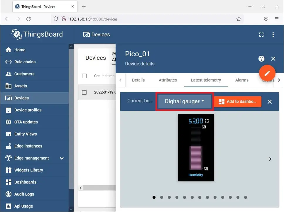
Also, navigation buttons will appear on right and left sides of the preview to change the appearance of the selected widget. In the end, the “Add to Dashboard” button will let you choose to create a new dashboard or add the widget to an existing one. I’ve created in my installation a new dashboard named “SmartFarm” and repeated the process for Temperature. The new dashboard will be available from the left menu on ThingsBoard console by selecting “Dashboards”, clicking the one just created and then “Open Dashboard”.
In the dashboard view, you will be able to edit and customize it from the pencil button on the bottom-right side of the screen:

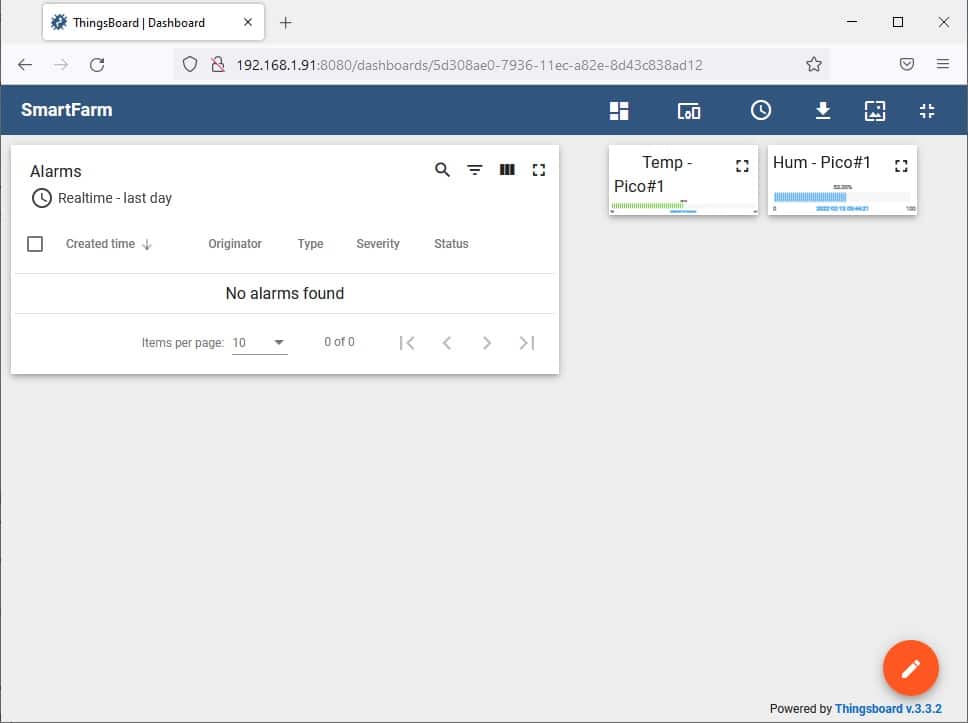
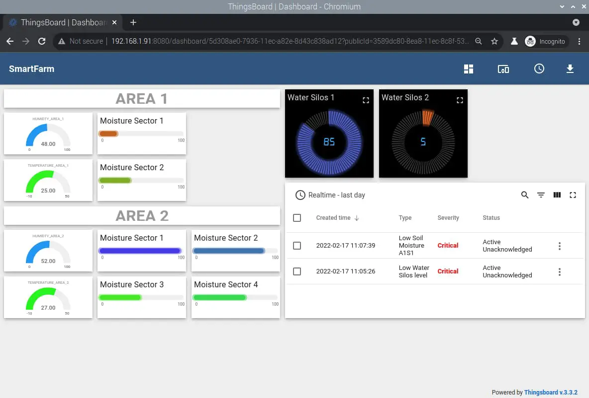
Besides resizing existing widgets, dragging them around the screen and customizing fonts, labels and so on, it will let you also add new widgets with the “Create new widget” button that will appear. For example, from here you can add an Alarm Widget showing active alarms. A first dashboard example will appear like the following picture:
You can also decide to create several dashboards, keeping some of them private and some public. From the Dashboards menu, you can make a dashboard public in order to show it without the need to login every time you need to show it (for example in our kiosk configuration). In this case, please select our dashboard on ThingsBoard and press the button “Make Dashboard Public”. The public link for your dashboard will appear:
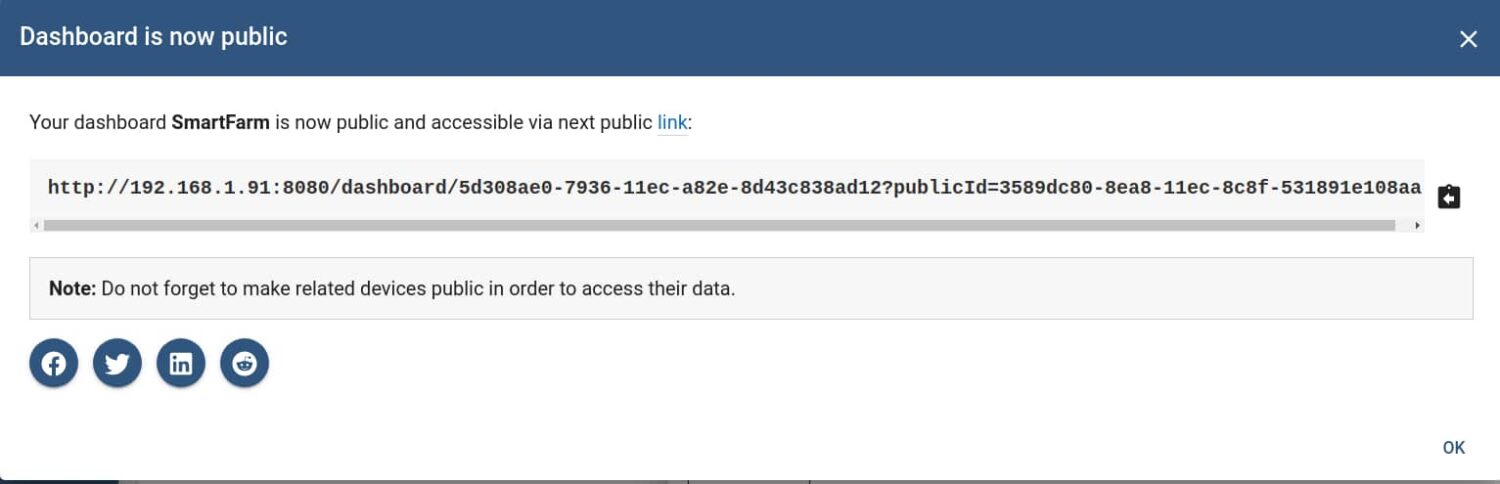
You will use this link in your Kiosk configuration. At the same time, to see data on the public dashboard you need to mark also your device as public (in the sense that data collected for this device from ThingsBoard are to be set as public). So, go to the devices list on ThingsBoard, select the device(s) to get appearing as public and mark it/them with the button “Make device public”.
A proof of concept of a kiosk showing the ThingsBoard dashboard can be the following picture:
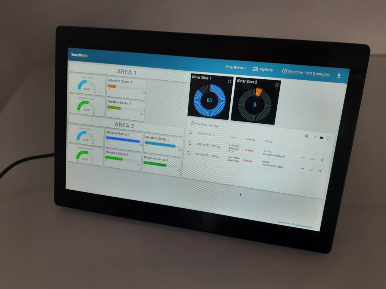
With the following dashboard screenshot:
Next steps
As already mentioned, getting the Raspberry PI Pico also wired with a solenoid valve will make it possible to you to automate the watering process so that irrigation will take place for shorter periods and only when needed. This will reduce the water used and better benefits will be getting with smaller sectors.
This project doesn’t deep into one of the next things to manage: how to power the WIZnet Ethernet HAT and Raspberry PI Pico located on your farm. Possible solutions are:
- keeping power cables going with Ethernet cables
- mixing and then splitting the 5V power within the Ethernet cable: it has some unused pins able to carry out power. Please note that this could reduce the max cable lenght because on long sections it may interfere with Ethernet data
- using a solar power panel: it would be the green solution
Once tested and get your prototype ready and working, you could also think about designing a PCB that includes the sensors you use and a specific slot for Raspberry PI Pico and WIZnet Ethernet HAT: this solution will give you a stronger product, easily replicable and with affordable costs.
As you can see from this project, having the WIZnet Ethernet HAT with Raspberry PI Pico enables you to create a world of applications, Moreover, added with the power of Raspberry PI computer boards and ThingsBoard, you can collect all the info coming from your IoT devices and show them into a cool and fully customizable dashboard.
This is just a proof of concept of what you can do with an Ethernet connection available to our Raspberry PI Pico. Your limits will be only imagination and the number/kind of sensors available.
Moreover, you can find cool projects with Raspberry PI devices in my Raspberry PI archives.
Enjoy!

Open source and Raspberry PI lover, writes tutorials for beginners since 2019. He's an ICT expert, with a strong experience in supporting medium to big companies and public administrations to manage their ICT infrastructures. He's supporting the Italian public administration in digital transformation projects.
![]()
![]()
![]()
![]()
![]()
![]()
![]()