
Last Updated on 13th April 2024 by peppe8o
In this tutorial, I’ll show how to perform I2C communication with two Arduino boards. The potentiometer and LCD are used to display the data sharing from a master Arduino to the slave one. The tutorial shows the simulation results for the potentiometer values read from the master and applied to the slave and vice versa, performed controlling the related LCD attached.
There are many devices which work on Inter-Integrated Circuit (I2C) protocols to share data with each other. The communication of the board is independent of the baud rate as of the USART.
Introduction
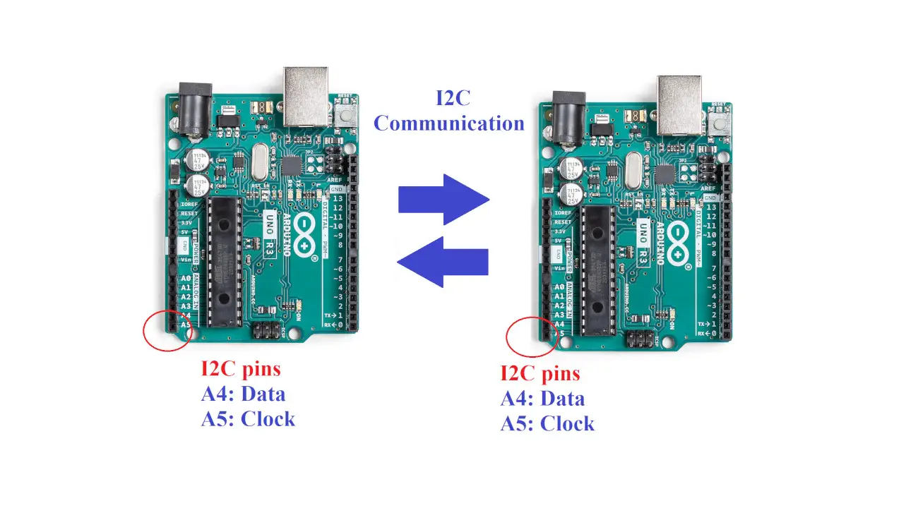
Inter-Integrated Circuit (I2C), also spelt IIC, is a synchronous, master/slave, packet-switched, single-ended serial communication bus that supports multiple controllers and targets. In order to transmit and receive data using the I2C protocol, it uses two lines: a serial clock pin (SCL), which pulses periodically by the Uno Controller (master) board, and a serial data pin (SDA), through which data pass between the transmitter and receiver.
So, the SDA line transfers data, and the SCL line synchronizes the devices with the clock signal.
Working Phenomena
The I2C Bus connects to two different sorts of devices: slave and master. The bus masters handle data transmission and reception to and from the slave devices. The master also provides the clock signal. The I2C protocol also supports multiple masters and multiple slaves, but in this tutorial, we’ll simplify with a single master and slave.
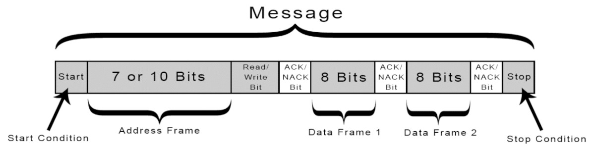
Each slave device connected to the I2C bus gets an exclusive 7-bit address. The master chooses a specific slave using this address to send or receive data, and the chosen slave reacts in accordance with the request.
What We Need

As usual, I suggest adding from now to your favourite e-commerce shopping cart all the needed hardware, so that in the end you will be able to evaluate overall costs and decide if continue with the project or remove them from the shopping cart. So, hardware will be only:
Check hardware prices with the following links:


Step-by-Step Procedure
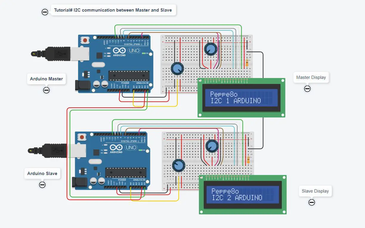
Wiring Diagram of Master and Slave Arduino board
The following wiring diagram gives the I2C communication between two Arduino boards (more info on ports can be found at Arduino pinout).
Each Arduino will read the value from its nearest potentiometer and send it to the other Arduino. The 2 potentiometers on the LCDs are just to control the contrast and don’t affect the read value variable.
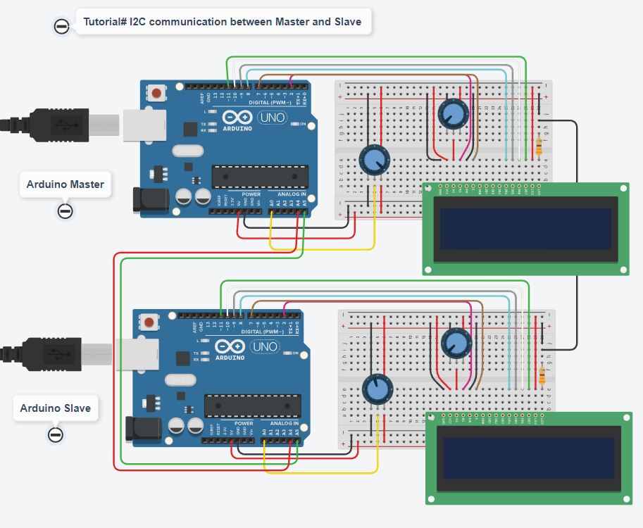
Please find below more wiring info:
- GND: GND of both boards need to connect together
- Master A4: Slave A4
- Master A5: Slave A5
- LCD wires are VCC=5V, GND= GND, rs=2, enable = 7, D4=8, D5=9, D6=10, D7=11 for both master and slave Contrast = Connected with a potentiometer to change the value for a contrast setting
- The potentiometer of both boards is connected at A0 of their board.
Get the code and Library for the I2C communication between Arduino
Connect your PC to Arduino and open Arduino IDE. For the very first steps, you can refer to Connecting Windows PC with Arduino tutorial. You can get the .ino code and libraries from my download area with the following link:
Our I2C test will use the Wire.h library, which is already included in our Arduino IDE.
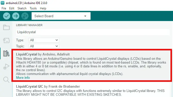
You also need to install the LiquidCrystal library, according to my Install Arduino Libraries: methods to add libraries with Arduino IDE tutorial, available from the Library Manager in Arduino IDE:
Code Explanation
Section 1: Master Code
We start by adding the I2C library, followed by the LCD library and its pins definition.
#include<Wire.h>
#include<LiquidCrystal.h>
LiquidCrystal lcd(2, 7, 8, 9, 10, 11);
In the setup, we open a the serial monitor at a baud rate of 9600 to visualize the data coming after receiving. The wire.begin() command enables an 8-bit data communication.
void setup()
{
  Serial.begin(9600);
  Wire.begin(8);
We also initialize our LCD with a welcome message that will last 5 seconds (5.000 milliseconds). Then, we’ll clear the LDC display in order to get it for receiving data:
  lcd.begin(16,2);                    //Initilize LCD display
  lcd.setCursor(0,0);                 //Sets Cursor at first line of Display
  lcd.print("Peppe8o");               //Prints Peppe8o in LCD
  lcd.setCursor(0,1);                 //Sets Cursor at second line of Display
  lcd.print("I2C 1 ARDUINO");         //Prints I2C ARDUINO in LCD
  delay(5000);                        //Delay 5 seconds
  lcd.clear();                        //Clear LCD display
}
In the loop section, the master requires to the I2C device with address “8” (our Arduino slave) 1 byte of data. We also start listening to the communication to get it stored in our MasterReceive variable. This will be the value that we’ll show in our Master LCD, received from the Slave:
void loop()
{
    Wire.requestFrom(8,1);
    byte MasterReceive = Wire.read();
On the other hand, the master must send its potentiometer value to the slave. So, we proceed to read the Master potentiometer value, mapping it from the raw 0-1023 range to a shorter 0-127 range, and then we’ll transmit it on the I2C port:
    int potvalue = analogRead(A0);
    byte MasterSend = map(potvalue,0,1023,0,127);

    Wire.beginTransmission(8);
    Wire.write(MasterSend);
    Wire.endTransmission();
All the data have been now shared between Master and Slave. The loop ends by managing their presentation on LCD (and in our serial monitor), finally adding a 500 milliseconds delay before running a new loop:
    lcd.setCursor(0,0);
    lcd.print(">>  Master  <<");
    lcd.setCursor(0,1);
    lcd.print("SlaveVal:");
    lcd.print(MasterReceive);
    Serial.println("Master Received From Slave");
    Serial.println(MasterReceive);
    delay(500);
    lcd.clear();
}
Section 2: Slave Code
Differently from Master, which has the control to initialize actions on I2C bus, the Slave will only react to actions executing 2 main functions:
- when the Master requires data, the Slave will execute the requestEvent() function
- when the Master sends data, the Slave will execute the receiveEvent() function
That said, the Slave code starts initializing the required libraries similarly to the master case:
#include<Wire.h>
#include<LiquidCrystal.h>
LiquidCrystal lcd(2, 7, 8, 9, 10, 11);
We also need a variable to store what values have been transmitted by Master, in order to get them from the receiveEvent() function and display them in our main loop:
byte SlaveReceived;In the Slave setup section, we again initialize the serial monitor and then we’ll register the Arduino slave board with address “8”:
void setup()
{
  Serial.begin(9600);
  Wire.begin(8);
As anticipated, we initialize the onReceive and onRequest actions, by referring them to the functions defined later in the code:
  Wire.onReceive(receiveEvent);
  Wire.onRequest(requestEvent);
Again, a welcome message will print for 5 seconds, before clearing the LCD to perform the I2C communication work:
  lcd.begin(16,2);
  lcd.setCursor(0,0);
  lcd.print("Peppe8o");
  lcd.setCursor(0,1);
  lcd.print("I2C 2 ARDUINO");
  delay(5000);
  lcd.clear();
}
The request event function starts getting the Slave potentiometer and mapping from 0 to 127. The result is sent to I2C for the master:
void requestEvent()
{
  int potvalue = analogRead(A0);
  byte SlaveSend = map(potvalue,0,1023,0,127);
  Wire.write(SlaveSend);
}
Similarly, the receive event gets the data from the I2C and stores it in the “SlaveReceived” variable:
void receiveEvent (int howMany)
{
   SlaveReceived = Wire.read();
}
In the main loop, the slave will just display on the LCD (and on the serial monitor) what is stored in our SlaveReceived variable:
void loop(void)
{
lcd.setCursor(0,0); //Sets Currsor at line one of LCD
lcd.print(">> Slave <<"); //Prints >> Slave << at LCD
lcd.setCursor(0,1); //Sets Cursor at line two of LCD
lcd.print("MasterVal:"); //Prints MasterVal: in LCD
lcd.print(SlaveReceived); //Prints SlaveReceived value in LCD received from Master
Serial.println("Slave Received From Master:"); //Prints in Serial Monitor
Serial.println(SlaveReceived);
delay(500);
lcd.clear();
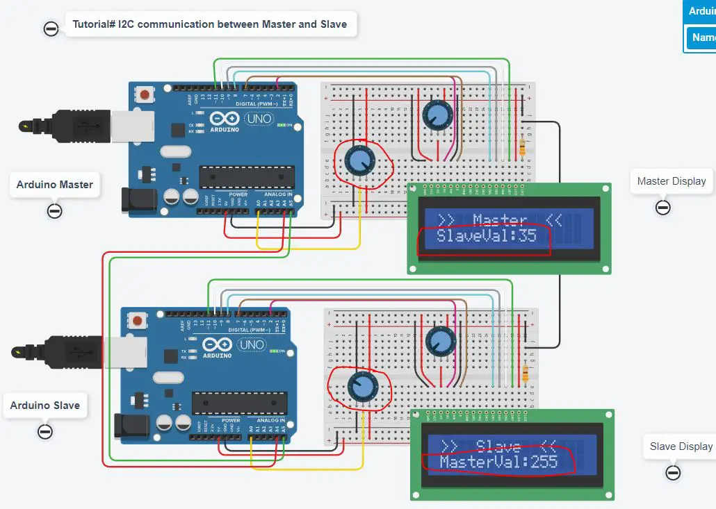
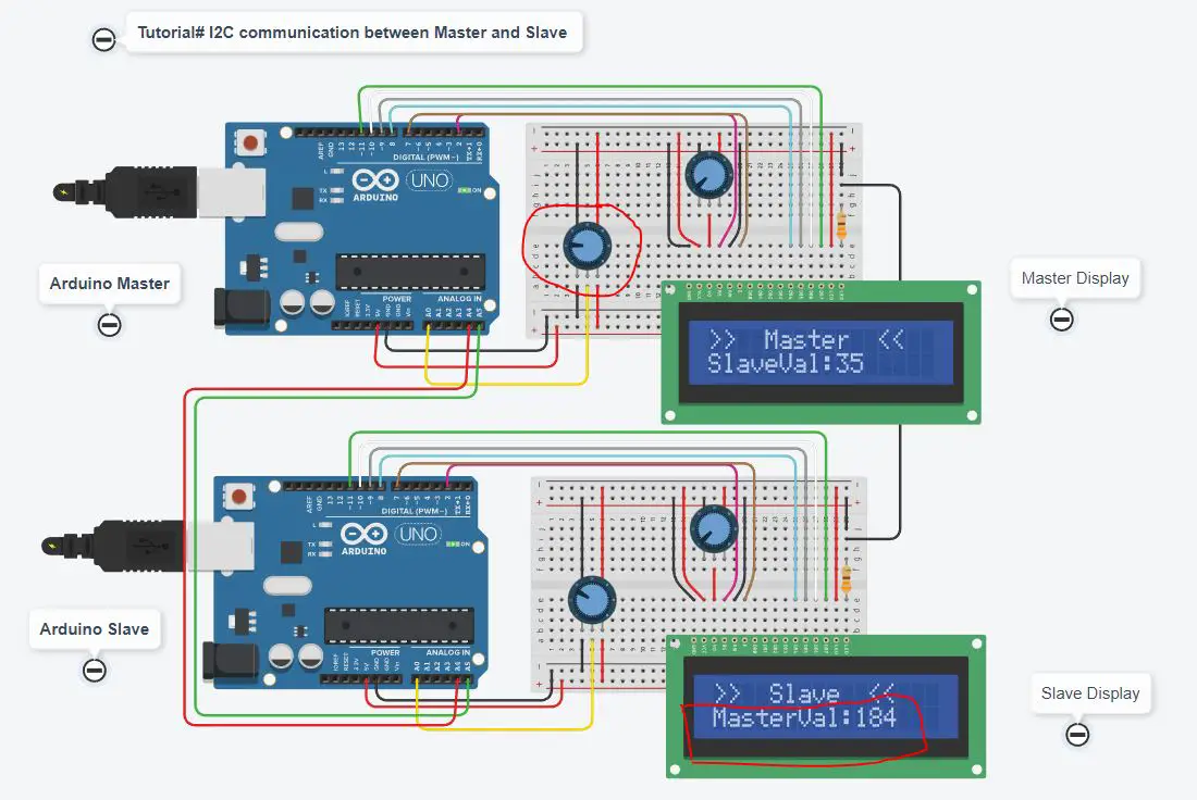
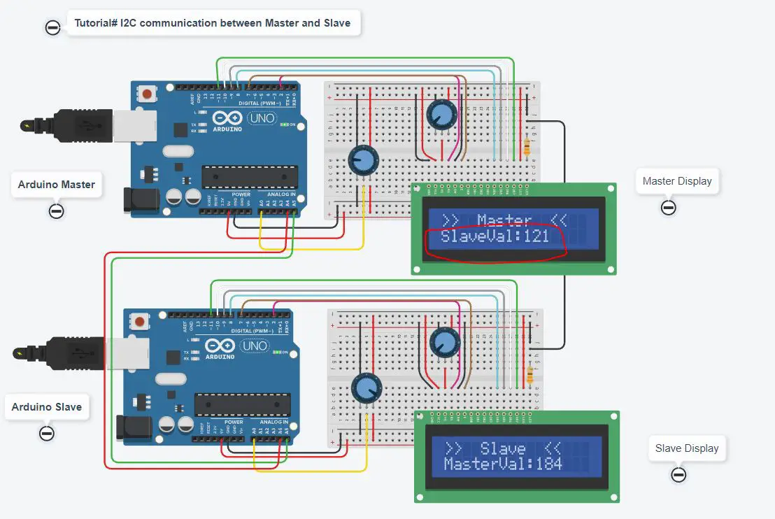
}Testing the I2C communication with Arduino Uno
When the potentiometer data from the master changes by rotating it, the changed data are sent to the slave to display on the slave LCD. Similarly, when the potentiometer at the slave rotates, values will show on the master LCD. The communication means between both boards I2C is set by pins A4 and A5.
What’s Next
Please find more tutorials on Arduino in peppe8o Arduino archives.
Enjoy!
Umar Jamil
For any queries and help with work, please contact me at:
Whatsapp: +92-346-661-7017/ Link
Email: umarjamil0007@gmail.com

I'm an Electronic Engineer, well-skilled to solve the issues of hardware and software. I do have laboratory which contains unlimited sensors and modules for testing the working. Also, I am experienced in Arduino programming, Android mobile application, microcontroller programming, IOTs and embedded projects. I provide services to control, realize the sensor data in the Mobile Application. For any queries and help for work Contact: Whatsapp:+92-346-661-7017 Email: umarjamil0007@gmail.com
![]()


