Last Updated on 2nd September 2023 by peppe8o
In this tutorial, I will show you how to connect and use 4 gear motors with Raspberry PI Pico using MicroPython and get the 4 main directions performed with single-line commands by defining the related custom functions.
Gear motors are the basis for every Raspberry PI Pico-based robot project. Managing them with a simplified code is a good way to start your car or tank prototype correctly
About Gear Motors
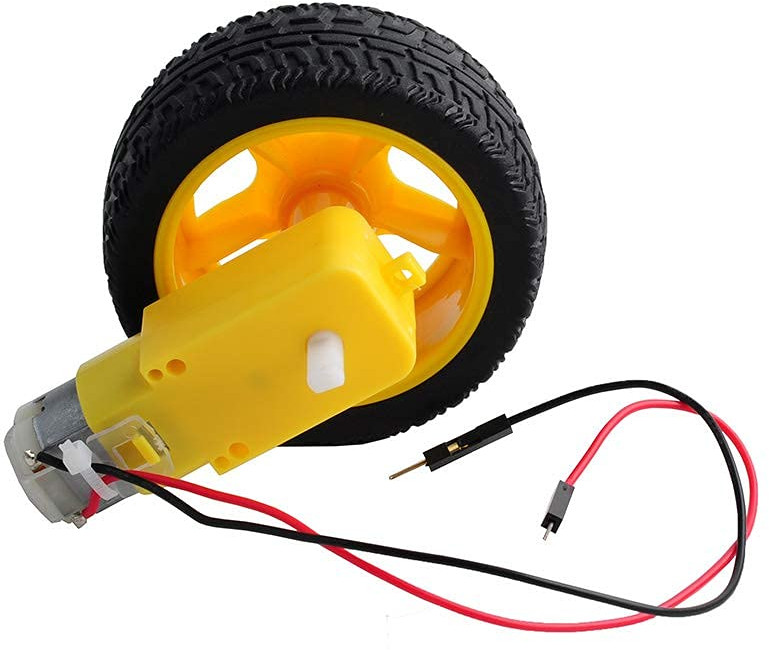
A gear motor (or geared motor) is a small electric motor, produced with an attached gear reducer. In the hobbyist world, the motor is usually made by a DC motor providing the rotation, while the gear system has a double function: both reducing the rotation speed, that otherwise would be too fast for controlling, and increasing the torque force, that increase the capacity to move heavier weights.
Applied to wheels, it makes it possible to move robots, tanks, and cars designed to perform different home functions.
The attached gears are usually made of plastic or aluminium. The plastic ones are enough for small projects with low force requirements, while higher requirements projects may need those made of aluminium.
Looking at the specs, you should put attention to the DC motor power requirements. With the Raspberry PI Pico able to provide up to 3,3V as output, the motor specs must accept this in their input range in order to get it working directly from RPI Pico pins. According to Raspberry PI Pico output, the gear motors able to run in a range of 3-6V are enough to be controlled directly. Of course, you can use an external power supply and control it from Raspberry PI Pico in order to get the gear motor powered with higher voltage, so reaching higher speed and torque.
Usually, the gear motor datasheet also provides the current drawn from it. This is another important parameter when calculating the current budget needed to power the project from batteries.
When using a gear motor, 2 wires are required for each motor, usually a black one and a red one. The common thinking may be to connect the black one to the ground and the red one to the power. But this configuration allows us to move the motor only in 1 direction. For double-direction spins, inverting the polarity of the power supply connection to the gear motor you will get the inverse rotation:
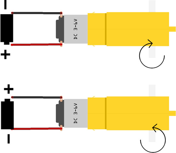
A smarter way to use the motor is connecting both the wires to Raspberry PI Pico-controlled pins and powering only one of them at time, in order to get performed both clockwise and counterclockwise rotations.
Finally, when installing the gear motor in your robot chassis, it is important to check the installation side: mounting the motor on the opposite side will result in the wheel rotating in the opposite direction. You can fix these cases bot inverting the wiring for the affected motor or mounting the motor on the opposite side.
For this tutorial, I will use 4 gear motors controlled by Raspberry PI Pico and an L293D chip. This chip allows us to make simpler the control and to choose to use Raspberry PI Pico power pins or an external power supply. A detailed explanation to use this chip with Raspberry PI Pico is available in my L293D and DC Motor with Raspberry PI Pico and MicroPython tutorial, where the L293D pinout is also available.
What We Need
As usual, I suggest adding from now to your favourite e-commerce shopping cart all the needed hardware, so that at the end you will be able to evaluate overall costs and decide if to continue with the project or remove them from the shopping cart. So, hardware will be only:
- A common computer (maybe with Windows, Linux or Mac). It can also be a Raspberry PI Computer board
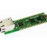
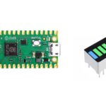
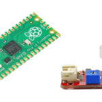
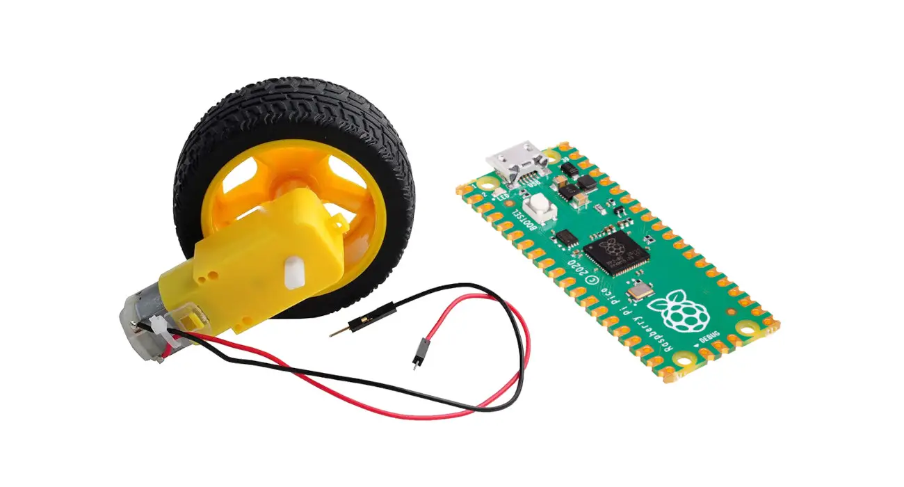
- Raspberry PI Pico microcontroller (with a common micro USB cable)
- gear motors
- L293D chip
- breadboard
- dupont wirings
Step-by-Step Procedure
Gear Motor and Raspberry PI Pico wiring with L293D
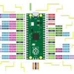
Please prepare the wiring as shown in the following picture, according to Raspberry PI Pico pinout. Please note that the L293D chip has a specific mounting tag, with the following diagram getting the L293D notch on the upper side:
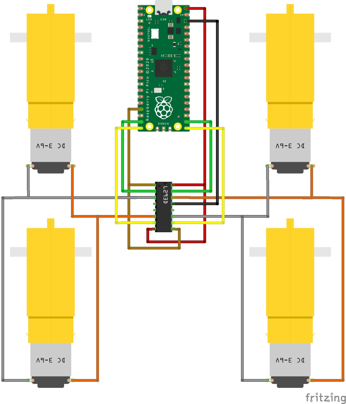
In order to get help with this wiring, please find below a table describing connections, where the gear motors are identified as left motors and right motors:
| RPI Pico | L293D | Left Gear Motors | Right Gear Motors |
| GP13 | 1,2 EN (1) | ||
| GP14 | 1A (2) | ||
| 1Y (3) | Negative Pole | ||
| 2Y (6) | Positive Pole | ||
| GP15 | 2A (7) | ||
| VBUS | Vcc2 (8) | ||
| GP13 | 3,4 EN (9) | ||
| GP16 | 3A (10) | ||
| 3Y (11) | Negative Pole | ||
| GND | GND (13) | ||
| 4Y (14) | Positive Pole | ||
| GP17 | 4A (15) | ||
| VBUS | Vcc1 (16) |
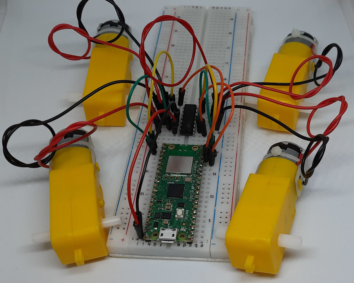
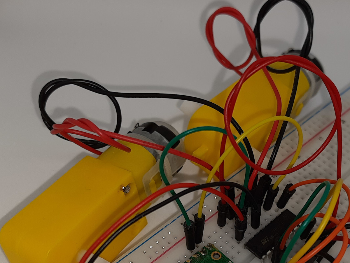
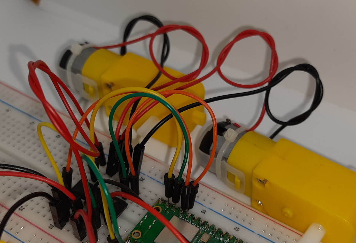
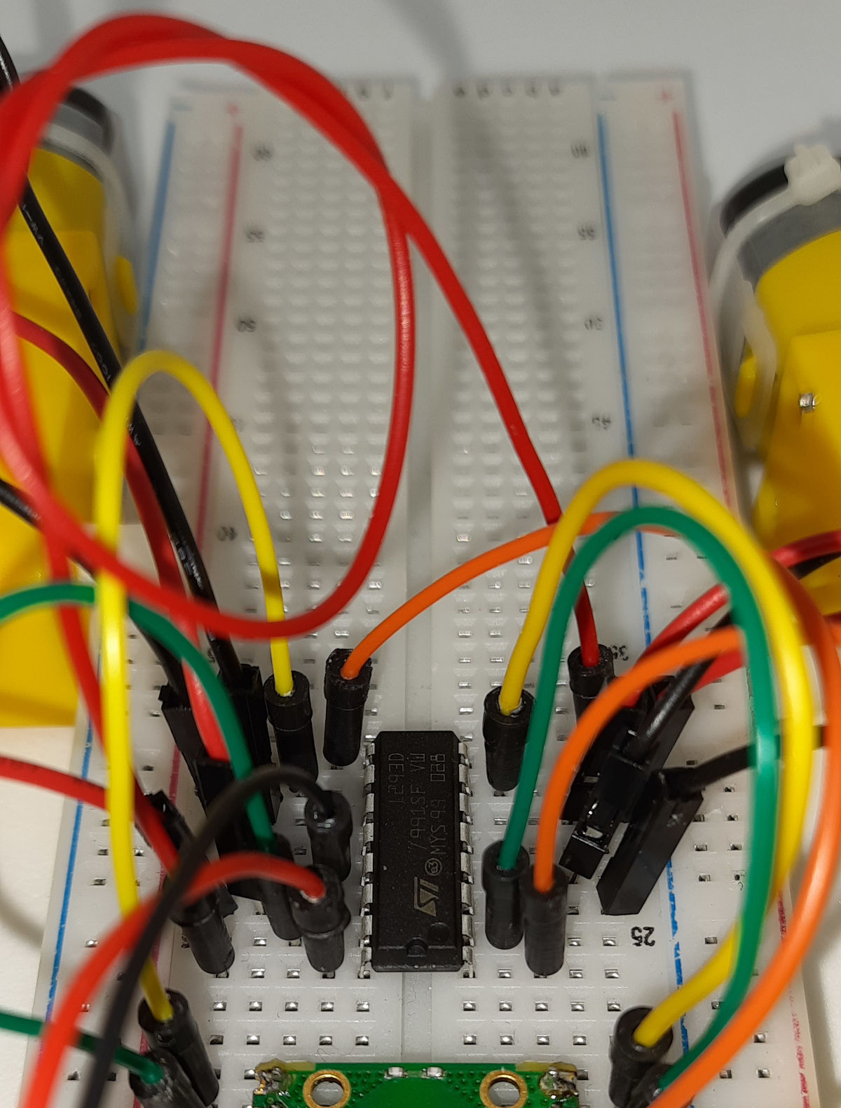
Please find below some pictures from my wiring:
Prepare Raspberry PI Pico and get MicroPython code
Connect RPI Pico to Thonny (you can refer to my tutorial about the First steps with Raspberry PI Pico).
Please download the code from the following link and save it to your Raspberry PI Pico storage:
The following lines will explain the code line by line.
In the beginning, we import the required modules:
from machine import Pin, PWM
from time import sleep
Then, we define the used PINs, according to our gear motor and Raspberry PI Pico wiring diagram. The pwmPIN is the one powering all the wheels with a PWM (Pulse Width Modulation) signal, while the other will control the clockwise and counterclockwise movement for each side (L=left, R=right):
pwmPIN=13

cwLPin=14
acwLPin=15

cwRPin=17
acwRPin=16
The motorMove() custom function works accordingly to what is already explained in my L293D and DC Motor with Raspberry PI Pico and MicroPython tutorial. I will re-use it in order to make simpler the movements in every direction. We’ll use this function to control each side gear motor pair. It can be useful to remember that:
- speed: is the input parameter (in percentage) that will control the power sent to our motors by controlling the PWM duty cycle
- direction: with a positive or negative number, we’ll control the clockwise or anti-clockwise rotation for our motors (wheels)
- speedGP: identify the Raspberry PI Pico PIN object giving power to our gear motors by a PWM signal
- cwGP: identify the Raspberry PI Pico PIN object setting the clockwise rotation
- acwGP: identify the Raspberry PI Pico PIN object setting the anti-clockwise rotation
def motorMove(speed,direction,speedGP,cwGP,acwGP):
  if speed > 100: speed=100
  if speed < 0: speed=0
  Speed = PWM(Pin(speedGP))
  Speed.freq(50)
  cw = Pin(cwGP, Pin.OUT)
  acw = Pin(acwGP, Pin.OUT)
  Speed.duty_u16(int(speed/100*65536))
  if direction < 0:
      cw.value(0)
      acw.value(1)
  if direction == 0:
      cw.value(0)
      acw.value(0)
  if direction > 0:
      cw.value(1)
      acw.value(0)
With this in mind, moving forward our wheels will be as simple as giving to sending commands for the gear motors of both sides to move forward. The speed parameter will remain an input for this function in order to make it configurable at every phase of your program in a simple way:
def move_f(speed):
    motorMove(speed,1,pwmPIN,cwRPin,acwRPin)
    motorMove(speed,1,pwmPIN,cwLPin,acwLPin)
In this way, moving forward with 100% of speed will be as simple as issuing the “move_f(100)” command.
The backward movement will result similar:
def move_b(speed):
    motorMove(speed,-1,pwmPIN,cwRPin,acwRPin)
    motorMove(speed,-1,pwmPIN,cwLPin,acwLPin)
Rotating our robot/car/tank in the right direction will mean just making the right-side motors move backwards and the left-side motors forward:
def move_r(speed):
    motorMove(speed,-1,pwmPIN,cwRPin,acwRPin)
    motorMove(speed,1,pwmPIN,cwLPin,acwLPin)
Similarly, for the left rotation:
def move_l(speed):
    motorMove(speed,1,pwmPIN,cwRPin,acwRPin)
    motorMove(speed,-1,pwmPIN,cwLPin,acwLPin)
Finally, the move_stop() custom function will stop any movement for our robot by deactivating all the motors:
def move_stop():
    motorMove(0,0,pwmPIN,cwRPin,acwRPin)
    motorMove(0,0,pwmPIN,cwLPin,acwLPin)
The final lines of this code will just give a usage example. These lines will perform the following sequential tasks:
- move forward for 2 seconds
- move backwards for 2 seconds
- rotate left for 2 seconds
- rotate right for 2 seconds:
move_f(100)
sleep(2)
move_b(100)
sleep(2)
move_l(100)
sleep(2)
move_r(100)
sleep(2)
move_stop()
Running the pico-gear-motor.py Script
Run this script in your Thonny IDE (F5) and you will start seeing your gear motors moving according to the set side and speed, then stopping.
What’s Next
Interested to do more with your Raspberry PI Pico? Try to look at my Raspberry PI Pico tutorials for useful and funny projects!
Enjoy!

Open source and Raspberry PI lover, writes tutorials for beginners since 2019. He's an ICT expert, with a strong experience in supporting medium to big companies and public administrations to manage their ICT infrastructures. He's supporting the Italian public administration in digital transformation projects.
![]()
![]()
![]()
![]()
![]()
![]()
![]()