
Last Updated on 13th April 2024 by peppe8o
In this tutorial, I will show you how to use the RFID with Arduino including the code, connection diagram and component list.
To make the attendance system for offices and schools, RFID-RC522 is a great module, as it can detect the tag from 10 cm.
In the general stores, the life of customers has been made easier with the help of RFID technology. Earlier people had to wait for hours to get the detailed bill for items they purchase. RFID tags on items store the information about the item and the RFID reader reads that information. Hence the bill preparation takes a very short time.
RFID is the abbreviation of Radio Frequency Identification, it is a technology with many applications in modern life.
How RFID Technology Works?
RFID or Radio Frequency Identification technology is composed of two components: a transponder (or tag) and a Transceiver (commonly known as reader). The transponder is attached to any item and important information related to that object is stored in it.
The reader contains a Radio Frequency module and an Antenna which is used to generate high frequency electromagnetic field. The reader tag is without a battery, that’s the reason that it’s a passive device. The tag has an antenna and microchip. The role of the microchip is to store and process the information and the function of antenna on the tag is to send and receive the signal.
In order to read the information stored in the tag, it should be near the RFID chip. The RFID reader is not bound to be in the line of sight of the tag. The chip generates an electromagnetic field, the antenna on the tag receives this signal and causes the electrons to flow through the chip, hence providing power to the chip. After getting powered the chip sends the stored information to the antenna of the tag. Then antenna of the tag sends this information to the reader and thus the information stored inside the tag is read by the reader.
Specifications of RFID (RC-522)
| Sr# | Specs | Value |
| 1. | Frequency Range | 13.56MHz |
| 2. | Communication interface | SPI/I2C/UART |
| 3. | Operating voltage | 2.5 V to 3.3 V |
| 4. | Maximum operating current | 13-26mA |
| 5. | Minimum operating current | 10uA |
| 6. | Inputs Logic | 5V tolerant |
| 7. | Read Range | 5cm |
Hardware Overview of RFID RC522 reader/writer
RC522 RFID Module is user friendly because it is easily available and at a very economical price. RC522 RFID Module comes with a card tag or key fob tag and memory is one KB. It is readable, but also writable: this means that you can write a secret message on the card. RC522 RFID Module creates an electromagnetic field of 13.56 MHz frequency. With the help of this electromagnetic field, the reader module communicates with the tag. The reader can communicate with any microcontroller through four wires SPI interface. RFID reader also supports I2C and UART interfaces.
There is an interrupt pin in the reader module, used to send a signal whenever there is a card or tag comes in proximity of the reader. The operating voltage of the reader module is between 2.5 volt and 3.3 volts but pins are 5v tolerant which means that reader can interface with any microcontroller specially Arduino.
RC522 RFID Module Pinout
RC522 RFID Module has 8 pins and with the help of these pins reader can communicate with the outside world.
VCC: This is the power pin of module having operating voltage between 2.5v and 3.3 volts. There is a 3.3 volt pin on Arduino where it can be connected. Connecting this pin to 5 volt pin of Arduino can damage the module.
RST: This pin is to reset the module.
GND: This is the ground pin of module it should be connected to the ground pin on Arduino.
IRQ: This is an interrupt pin. Whenever tag comes in proximity of the RFID reader through this pin an interrupt generate to wake up the controller.
MISO (Master In Slave Out)/ SCL/Tx: This pin is self-explanatory, master in slave out means this is pin where the output pin of the slave connects with the master’s input while dealing with an SPI interface. This pin can act as a clock pin when I2C interface is used. For UART interface, this pin acts as a transmitter.
MOSI (Master Out Slave In): This is the pin which is output of master and input of slave. Hence the master’s output connect as an input to slave device.
SCK: This is the clock pin. The master device (Arduino) sends the clock pulses through this pin.
SS/ SDA/ Rx: While using the SPI communication protocol this pin is slave select. Meaning this pin is active low for a device to receive data from slave. In other words, the slave select pin of concern device gives lower level logic to receive data from a master device. Also this pin acts as a serial data pin when communication is done using I2C protocol. While dealing with UART protocol this pin acts as receiver pin of the module.
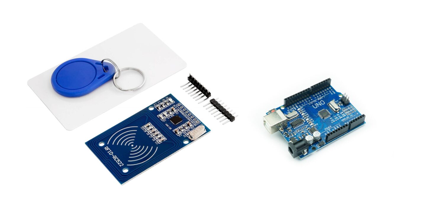
What We Need?
As usual, I suggest adding from now to your favourite e-commerce shopping cart all the needed hardware, so that at the end you will be able to evaluate overall costs and decide if to continue with the project or remove them from the shopping cart. So, hardware will be only:
Check hardware prices with the following links:


Step-by-Step Procedure
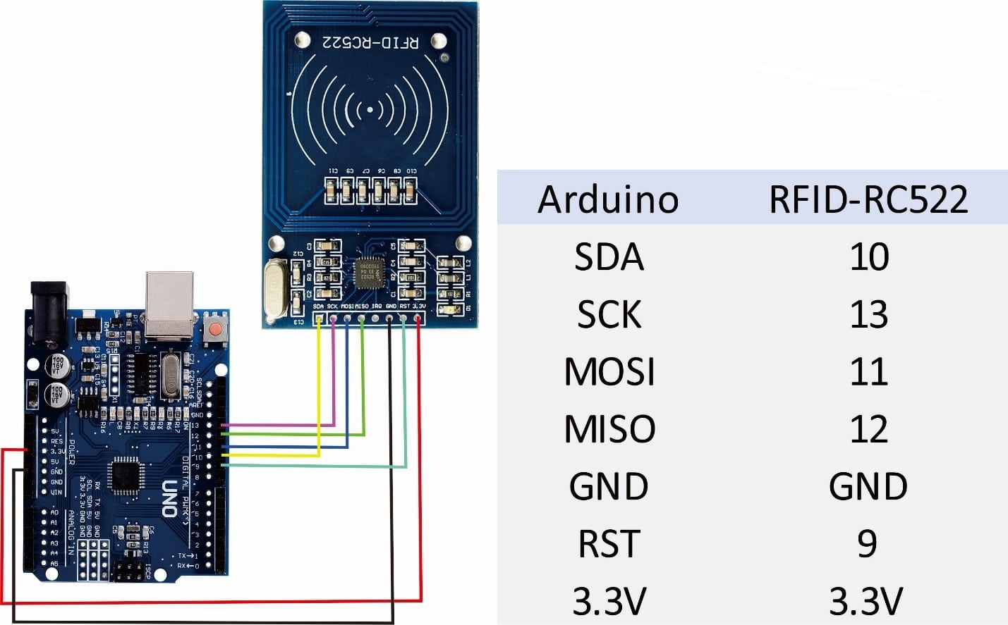
Wiring Diagram of RFID with Arduino
As shown in the image below, the module connects with Arduino Uno. Please follow the wiring that is presented in the picture, according to Arduino Uno Pinout. The picture also gives a detailed table.
Get RFID.ino, library and Code Explanation
Connect your PC to Arduino and open Arduino IDE. For the very first steps, you can refer to Connecting Windows PC with Arduino tutorial. You can get the .ino code and library from my download area with the following link:
You also need to install the following library, according to my Install Arduino Libraries: methods to add libraries with Arduino IDE tutorial:
This RFID works on SPI protocol, so the SPI library includes related pins defined. In Arduino Uno, SPI pins are 10, 11, 12, 13. By adding the SPI library, the other pins are activated by default.
#include <SPI.h>
#include <MFRC522.h>
#define SS_PIN 10
#define RST_PIN 9

MFRC522 mfrc522(SS_PIN, RST_PIN);
In the setup, serial monitor is initialized at a 115200 baud rate. SPI and RFID chip are initialized.
void setup()
{ Serial.begin (115200);
  SPI.begin();          // Initiate  SPI bus
  mfrc522.PCD_Init();   // Initiate MFRC522

}
In the loop section, when the tag is placed in front of the RFID chip, it is detected due to frequency resonance. Each tag has a unique ID which is read by the RFID chip by the command mfrc522.PICC_IsNewCardPresent(). It checks the availability of the card, while mfrc522.PICC_ReadCardSerial() read out the values like size of the card address. After the address size is read, the code prints it on the serial monitor.
void loop()
{
  if ( ! mfrc522.PICC_IsNewCardPresent())
  {
    return;
  }
  if ( ! mfrc522.PICC_ReadCardSerial())
  {
    return;
  }
  Serial.print("UID:");
  String content = "";
  byte letter;
  for (byte i = 0; i < mfrc522.uid.size; i++)
  { //Show UID on serial monitor
    Serial.print(mfrc522.uid.uidByte[i], HEX); // Serial.print("UID tag :");
    content.concat(String(mfrc522.uid.uidByte[i] < 0x10 ? " 0" : " "));
    content.concat(String(mfrc522.uid.uidByte[i], HEX));
  }
  content.toUpperCase();
}
What’s Next
Please find more tutorials on Arduino in peppe8o Arduino archives.
Enjoy!
Umar Jamil
For any queries and help for work, please contact me at:
Whatsapp: +92-346-661-7017
Email: umarjamil0007@gmail.com

I'm an Electronic Engineer, well-skilled to solve the issues of hardware and software. I do have laboratory which contains unlimited sensors and modules for testing the working. Also, I am experienced in Arduino programming, Android mobile application, microcontroller programming, IOTs and embedded projects. I provide services to control, realize the sensor data in the Mobile Application. For any queries and help for work Contact: Whatsapp:+92-346-661-7017 Email: umarjamil0007@gmail.com
![]()


