
Last Updated on 13th April 2024 by peppe8o
In this tutorial, we’ll interface the GY-61 accelerometer with Arduino Uno including code, connection diagram, and component list.
To control things through gesture movement, GY-61 is a great and cheap way module enabling to manage all three directions moments
The ADXL335 (GY-61) Accelerometer
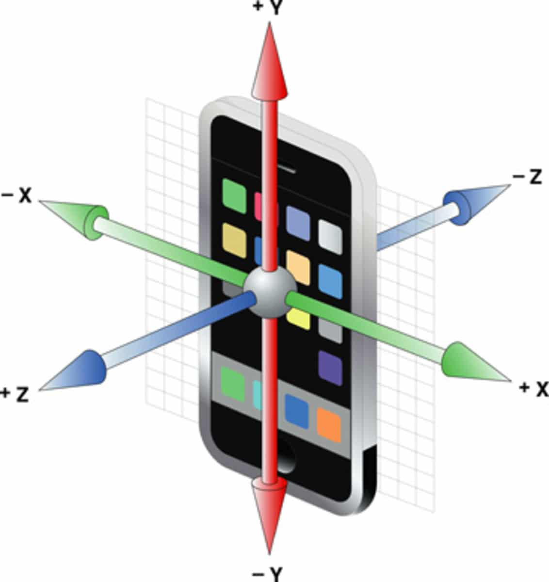
An accelerometer is a device that measures the force of acceleration due to gravity along the X, Y and Z axis. It applies in all the applications requiring tilt sensing. The accelerometer measures the acceleration and produces a voltage proportional to the acceleration. Any microcontroller with analog PINs can read this voltage.
In mobile phones, the secret weapon, behind detecting the auto rotation of the screen or tilt sensing used in playing games, is the accelerometer. It is widely applied in low power, cost effective, motion and tilt sensing applications like mobile phones and gaming systems etc.
Working Principle of Accelerometer
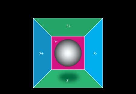
In order to understand the working of an accelerometer, using an example will help us to better understand the physical principle. Consider a ball inside a cube and somehow suspended in the air. If we apply a force in such a way that the ball moves towards the left side with the acceleration 1g (1g acceleration is equivalent to 9.8 m/s2 gravitational acceleration), the ball will hit the wall X with the measured acceleration will be equal to 1g. So in this case value of X will be 1 while the value of Y and Z axis will be zero.
Now in another case, if we put the cube to the surface of the ground, then the ball will hit the Z wall with 1g force along the Z-axis. Again here the value of Z is 1 and the value of X and Y is 0:
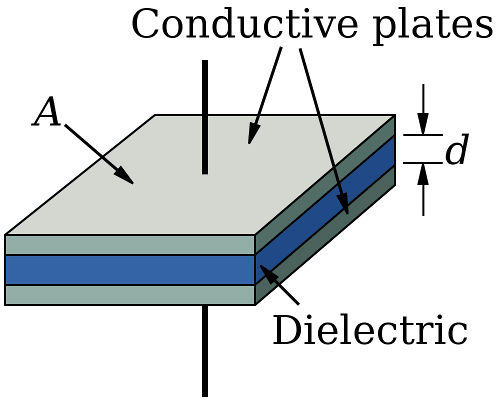
The accelerometer has a specific chip sort of structure designed on its surface which has the capability to measure the acceleration. There are two types of plates in this structure: one fixed plate and the other are held by a spring that deflects by acceleration. Poly silicon springs hold the structure. The structure has the ability to deflect whenever we apply acceleration on any particular axis. For example, whenever acceleration applies along the x-axis, the springs holding the structure deflect and in this way it detects the acceleration along x axis. The same is the case for all other axes. As a result of deflection the capacitance between the fixed plates and the plates suspended by springs, changes. The amount of change brought in capacitance is in proportion to the amount of acceleration or deflection caused along any axis.
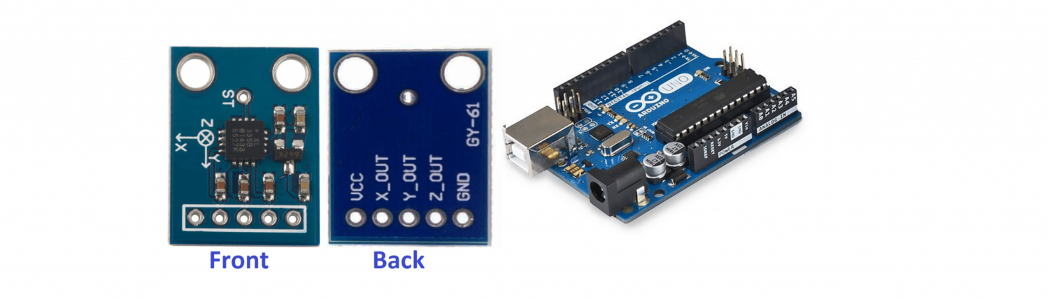
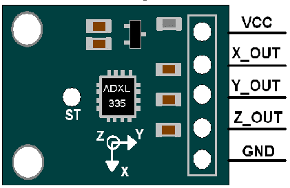
Hardware Description and Pinout
The accelerometer has a sensing range between -3g to 3g. The sensor has the ability to measure dynamic acceleration as well as static acceleration, the latter being due to gravity or s tilt sensing. Motion, shock or vibration produce dynamic acceleration.
ADXL335 (MPU 6050) works on voltage in a range between 1.8 volt and 3.6 volt. It consumes 350 microampere. As the 3.3 volt pin is available on Arduino Uno, it becomes very suitable to interface with our microcontroller. The pins providing the value for x-axis, y-axis and z-axis acceleration value can be read by Arduino.
VCC: This is the power pin. From Arduino Uno 3.3 volt or 5 volt connect on this pin.
XOUT: X out pin outputs the analog value produced in proportion to acceleration along X axis.
YOUT: Y out pin outputs the analog value produced in proportion to acceleration along Y axis.
ZOUT: Z out pin outputs the analog value produced in proportion to acceleration along Z axis.
GND: This ground pin connects to the ground pin on Arduino Uno.
ST (SELF TEST): Self-test pin enables us to check whether sensor is functioning or not
What We Need
As usual, I suggest adding from now to your favourite e-commerce shopping cart all the needed hardware, so that at the end you will be able to evaluate overall costs and decide if to continue with the project or remove them from the shopping cart. So, hardware will be only:
- Arduino Uno Board
- ADXL335 (GY-61) Accelerometer
- breadboard
- dupont wirings
Check hardware prices with the following links:


Step-by-Step Procedure
Connection with Arduino
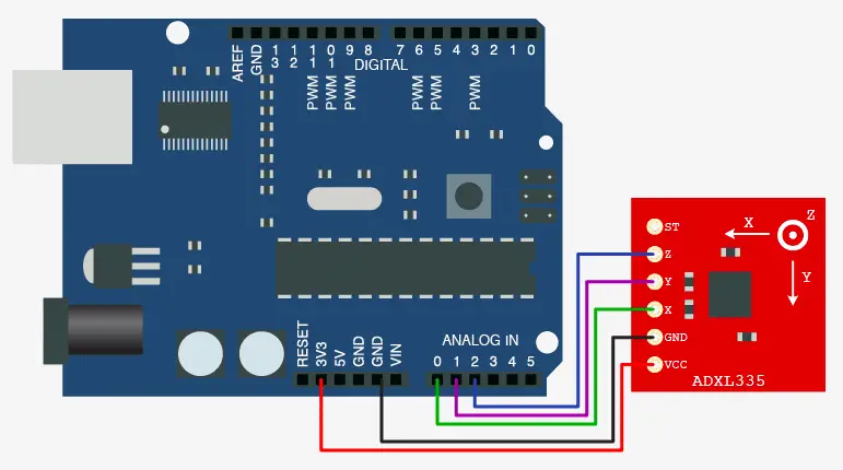
As shown in the image below, the sensor connect with Arduino Uno. Please follow wiring that, according to Arduino Uno Pinout to make the connections.
Arduino PIN >> ADXL PIN:
Connection of Arduino with ADXL 335 is not that much difficult. Given below is image which is self-explanatory. Vcc pin connect with 3.3v pin on Arduino Uno and GND pin on sensor connect with the ground pin on Arduino. X OUT, Y OUT, Z OUT pins are connect on analog pins of Arduino namely A0, A1 and A2.
Get Accelerometer.ino and Code Explanation
Connect your PC to Arduino and open Arduino IDE. For the very first steps, you can refer to Connecting Windows PC with Arduino tutorial. You can get the .ino code from my download area with the following link:
The code starts with lines where we declare the input analog pins. As the ADC of Arduino is 10 bit, so maximum and minimum values are given the value 0 and 1023 under variables RawMin and RawMax.
The “sampleSize” constant will create axes readings with an average calculation on a number of samples (10). This allows for avoiding temporary readings that may affect the device’s precision.
In the setup function, we initialize the serial monitor with a 9600 baud rate.
const int xInput= A0;
const int yInput= A1;
const int zInput= A2;
int RawMin=0;
int RawMax=1023;
const int sampleSize = 10;

void setup()
{
Serial.begin(9600);
}
Now in the loop section, the first line reads the x input (value of acceleration along x axis) and stores it in a variable named “xRaw”. The ReadAxis() function is a custom function that will be described later in the code.
void loop()
{
int xRaw = ReadAxis(xInput);
int yRaw = ReadAxis(yInput);
int zRaw = ReadAxis(zInput);
Then using the following line in the code the value map between -3000 and 3000. For example if the value of “xRaw” is 0 then the value of “xScaled” will be -3000 and incase if the value is maximum then “xScaled” will be having value 3000. The same is the case for yScaled and zScaled.
long xScaled = map(xRaw, RawMin, RawMax, -3000,3000);
long yScaled = map(yRaw, RawMin, RawMax, -3000,3000);
long zScaled = map(zRaw, RawMin, RawMax, -3000,3000);
Now in the variable xScaled, yScaled and zScaled divide by 1000 and hence their value becomes between -3 to 3 which is range of sensor.
float xAccel = xScaled/1000.0;
float yAccel = yScaled/1000.0;
float zAccel = zScaled/1000.0;
Now these variables named ‘xAccel, yAccel, zAccel’ are the values for gravitational acceleration along x, y and z axis. Their values display on the serial monitor.
Serial.print("X, Y, Z :: ");
Serial.print(xRaw);
Serial.print(", ");
Serial.print(yRaw);
Serial.print(", ");
Serial.print(zRaw);
Serial.print(" :: ");
Serial.print(xAccel,0);
Serial.print("G, ");
Serial.print(yAccel,0);
Serial.print("G, ");
Serial.print(zAccel,0);
Serial.print("G, ");
delay(200);
}
Finally, the ReadAxis() function definition. As you can see from the code, it simply reads the PIN analog value and repeats the measurement a number of times equal to the “sampleSize” value (10), summing it to the local variable “reading”. At the end of the function, before returning the read value to the main loop, the we divide the result by “sampleSize” to get the mathematical average:
int ReadAxis(int axisPin)
{
long reading=0;
analogRead(axisPin);
delay(1);
for(int i=0; i< sampleSize;i++)
  {
  reading += analogRead(axisPin);
  }
return reading/sampleSize;
}
What’s Next
Please find more tutorials on Arduino in peppe8o Arduino archives.
Enjoy!
Umar Jamil
For any queries and help for work, please contact me at:
Whatsapp: +92-346-661-7017
Email: umarjamil0007@gmail.com

I'm an Electronic Engineer, well-skilled to solve the issues of hardware and software. I do have laboratory which contains unlimited sensors and modules for testing the working. Also, I am experienced in Arduino programming, Android mobile application, microcontroller programming, IOTs and embedded projects. I provide services to control, realize the sensor data in the Mobile Application. For any queries and help for work Contact: Whatsapp:+92-346-661-7017 Email: umarjamil0007@gmail.com
![]()


