Last Updated on 7th July 2024 by peppe8o
In this tutorial I will show you how to use the 1602 LCD with Raspberry PI computer board, adding a 2-lines text display to your projects.
This article will show you how to control the 1602 LCD with a Raspberry PI computer board. If you need to use the display with a Raspberry PI Pico, please refer to my Using I2C LCD display With Raspberry PI Pico and MicroPython tutorial.
About I2C LCD 1602 Display
The Liquid Cristal Display (LCD) device includes a variable number of text lines and columns. When you power on the display, you can see the text “boxes”, each allowing you to show a single character. This display model is common for DIY projects as it lets you show any text with a low-cost device.
There are different versions of this display in the market, but most of them are based on the Hitachi HD44780. You can find the producer datasheet at the following link: hitachi-hd44780-datasheet.pdf. This display comes with the characters already saved in their memory, so you don’t have to create the main characters from a binary array. Nevertheless, the HD44780 also allows you to create your custom characters and save them into a specific memory area (up to 8 custom characters).
The base version has 16 PINs and you must connect these ports (quite all) to your Raspberry PI to control them. These PINS are in the top-right side of the picture shown below:
This model requires to manage the timing and the data to transmit as described in the datasheet.
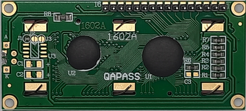
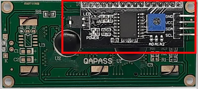
With time, many producers started to add a chip on the back of this display to make it simpler to interface and control them from an I2C interface. Adafruit, for example, added the MCP23008 chip that we’ll identify in the next paragraphs as it shows you a 0x20 i2c address. Other 1602 display versions are based on the MCP23017, which shows you a 0x27 i2c address. Moreover, the backpack added to the display usually brings you a potentiometer to adjust the screen contrast with a screwdriver. These LCD models appear on the back side as shown in the following picture:
This tutorial will show you how to use the version with the I2C backpack.
What We Need
As usual, I suggest adding from now to your favourite e-commerce shopping cart all the needed hardware, so that at the end you will be able to evaluate overall costs and decide if to continue with the project or remove them from the shopping cart. So, hardware will be only:
- Raspberry PI Computer Board (including proper power supply or using a smartphone micro USB charger with at least 3A)
- high speed micro SD card (at least 16 GB, at least class 10)
- I2C LCD Display
- Dupont wirings
- Breadboard
Step-by-Step Procedure
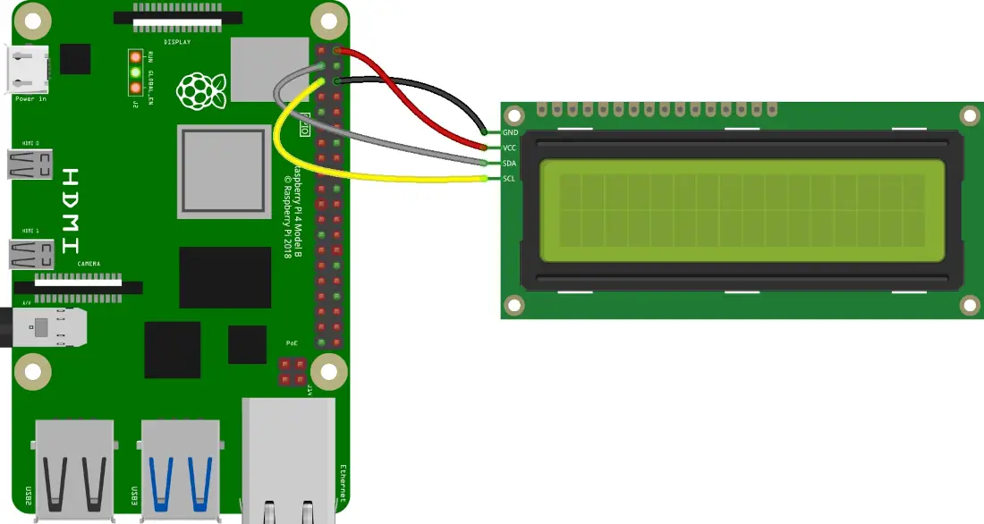
I2C 1602 LCD and Raspberry PI Wiring Diagram
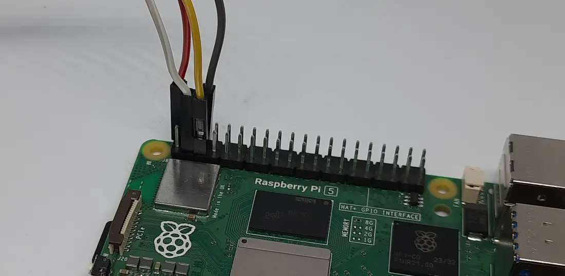
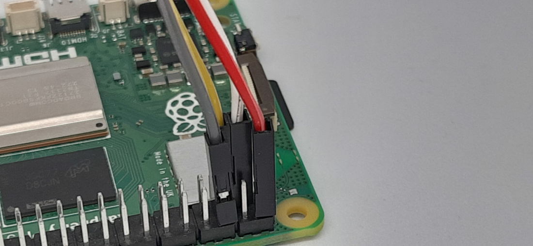
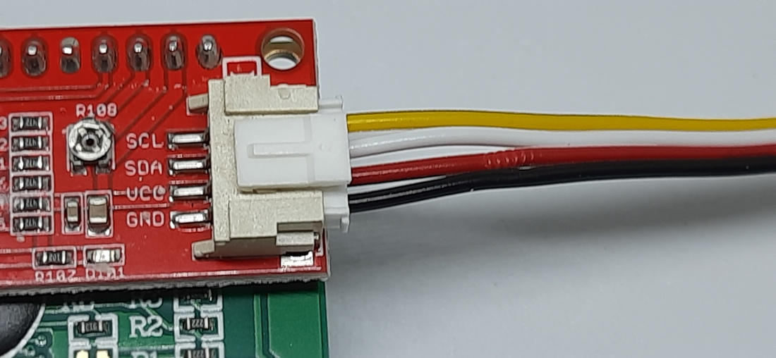
Please connect the 1602 i2c display to the Raspberry PI as shown in the following picture, according to the Raspberry PI Pinout:
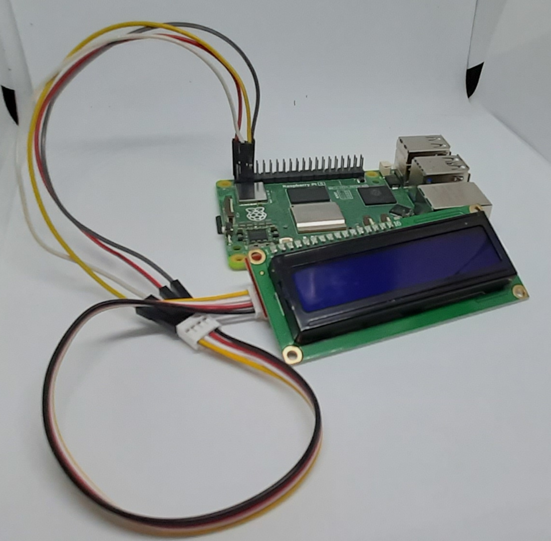
Please find below some pictures from my lab. I used an i2c 1602 LCD display with connectors for a base shield, but I wired them with 4 Dupont wires to show you how to arrange the connections:
Prepare the Raspberry PI Operating System
The first step is installing the Raspberry PI OS Lite (I suggest the 64-bit version, for boards supporting it) to get a fast and light operating system (headless). If you need a desktop environment, you can also use the Raspberry PI OS Desktop, in this case working from its terminal app. Please find the differences between the 2 OS versions in my Raspberry PI OS Lite vs Desktop article.
Please make sure that your OS is up to date. From your terminal, use the following command::
sudo apt update -y && sudo apt upgrade -yWe also need some additional packages to install:
sudo apt install python3-pip python3-smbus i2c-tools -yEnable the Raspberry PI I2C Interface
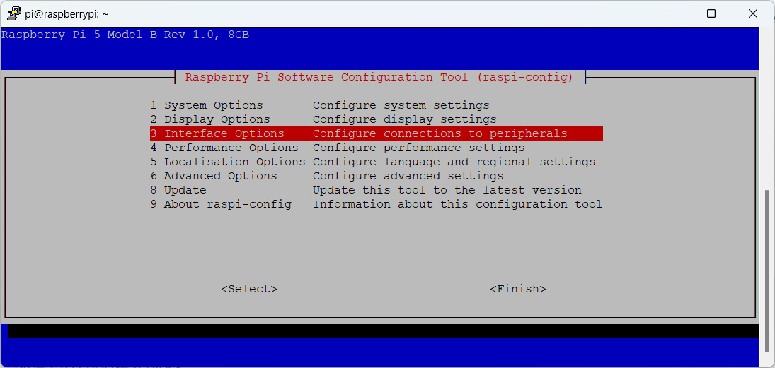
We also need to enable the I2C interface in our Raspberry PI from the raspi-config tool. Please use the following command to enter in it:
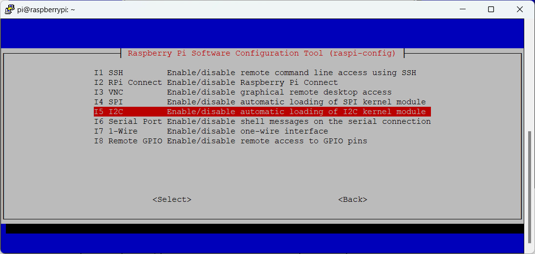
sudo raspi-configFrom the raspi-config home page, please select the “Interface Options” selection:
The identify and select the “I2C” option:
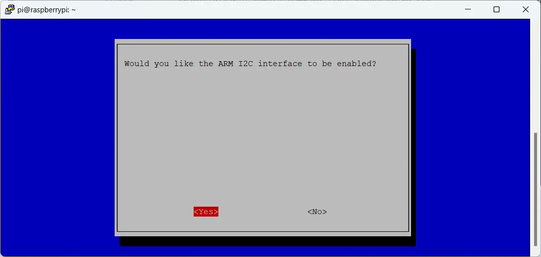
Move the cursor to “YES” to enable the interface:
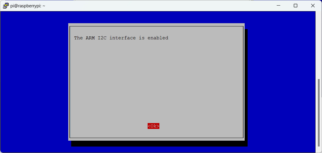
In the following screen, please confirm the interface enabled message:
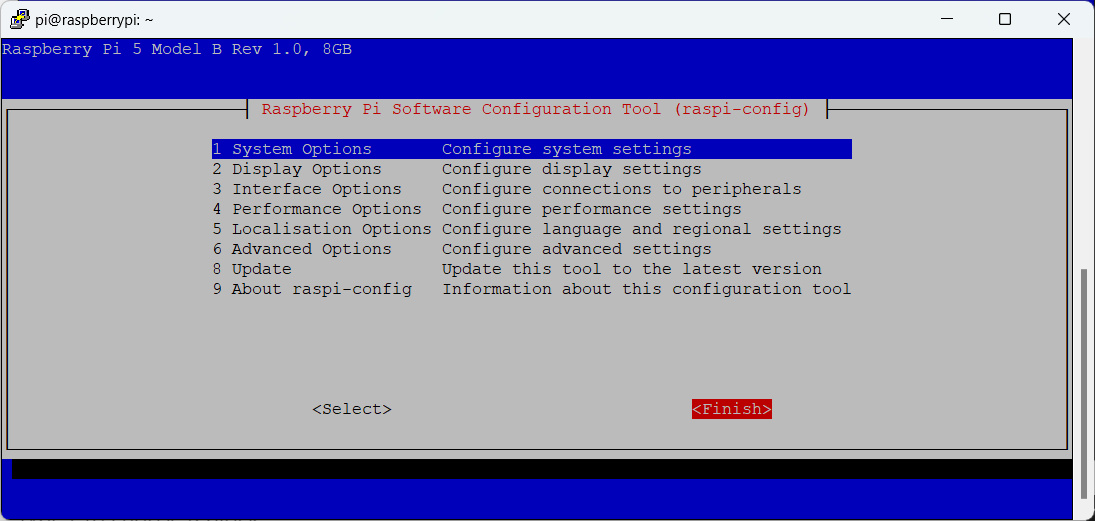
Finally, back to the raspi-config home screen, please select “Finish”:
At the end, I suggest to reboot your Raspberry PI to have the I2C interface enabled:
sudo rebootWith the i2cdetect command, we can check that everything is running correctly. In the following command, the -y disables interactive mode and the 1 specifies the I2C bus.
(my_project) pi@raspberrypi:~ $ i2cdetect -y 1
     0  1  2  3  4  5  6  7  8  9  a  b  c  d  e  f
00:                         -- -- -- -- -- -- -- --
10: -- -- -- -- -- -- -- -- -- -- -- -- -- -- -- --
20: 20 -- -- -- -- -- -- -- -- -- -- -- -- -- -- --
30: -- -- -- -- -- -- -- -- -- -- -- -- -- -- -- --
40: -- -- -- -- -- -- -- -- -- -- -- -- -- -- -- --
50: -- -- -- -- -- -- -- -- -- -- -- -- -- -- -- --
60: -- -- -- -- -- -- -- -- -- -- -- -- -- -- -- --
70: -- -- -- -- -- -- -- --
Please note the detected address: “20”, which means 0x20 (binary number expressed in decimals). Please note that this tutorial could not work if you find a different address.
Install the Adafruit Charlcd Package
With the latest Python versions, we must use virtual environments with Raspberry PI to install external libraries (please refer to the link for a complete guide). So, let’s create our virtual environment (I named it “my_project, but you can give it whatever name:
python3 -m venv my_project --system-site-packagesLet’s activate the virtual environment:
source ./my_project/bin/activatePlease note that you must activate the environment every time you use the libraries installed in it if you deactivate the environment and/or reboot your Raspberry PI.
Let’s install the Adafruit library needed to manage our LCD display:
pip3 install adafruit-circuitpython-charlcdTest the 1602 LCD with Raspberry PI
Please note that you must have the virtual environment active before running these tests.
Let’s prepare our first test, a simple “Hello world” message from peppe8o. You can download the script from my download area in your Raspberry PI:
wget https://peppe8o.com/download/python/lcd/i2c-lcd-test-01-hello-world.pyLooking at this code, we find the initial lines which import the required libraries:
import board
import busio
import adafruit_character_lcd.character_lcd_i2c as character_lcd
Then the LCD initialization comes. Here, the code initializes the i2c communication object. Then the code sets the number of columns and rows according to the LCD model. If you have more columns and rows in your display, please set it here.
Then script creates the “lcd” object that we’ll use to control the display:
i2c = busio.I2C(board.SCL, board.SDA)
cols = 16
rows = 2
lcd = character_lcd.Character_LCD_I2C(i2c, cols, rows, address = 0x20)
The previous part should be included in every script. The following part will show you some usage examples and will vary in the following examples.
In this example, we’ll use the following LCD commands:
- lcd.message = “text”: this command will print on the display any character text you will put in the brackets;
- lcd.cursor_position(column,row) [“column” and “row” are integer numbers]: this command will position the cursor at the specified coordinates. Please note that both row and column numbering start from 0;
- lcd.clear(): it clears the display, cleaning all the previously printed text;
- lcd.backlight = False [or True]: this command disables or enables the display backlight.
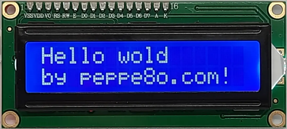
So, the final part of our first test follows:
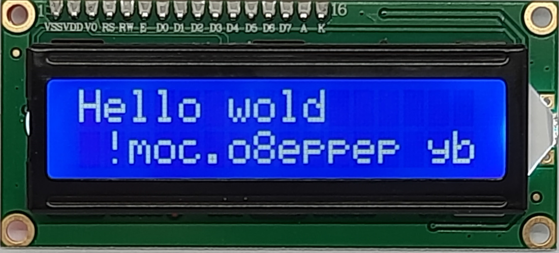
try:
  lcd.message = "Hello wold"
  lcd.cursor_position(0,1)
  lcd.message = "by peppe8o.com!"

except KeyboardInterrupt:
  lcd.clear()
  lcd.backlight = False
In the “try” section, the script will print a “Hello world by peppe8o.com!” message divided into 2 lines. Here we’re manually positioning the cursor on the second line with the “lcd.cursor_position” command. Anyway, please note that the display will automatically split the message at the end of the first line.
Another way to move to a new line is by using the special character “\n” in your text string. This character (with the “\” escape symbol) equals to a carriage return.
The final “except” section will manage any occurring interrupt (CTRL+C) from the user, closing the program with a cleaning of the display and powering off the backlight.
You can run this example with the following command:
python3 i2c-lcd-test-01-hello-world.pyThe following picture shows the result:
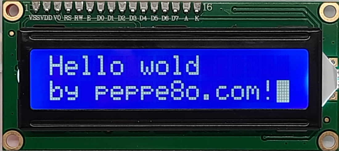
Test 2: Blinking the Cursor
In this test we’ll add the following command:
- lcd.blink = True [or False]: this command will make the cursor blinking
For this test, you can download the following script:
wget https://peppe8o.com/download/python/lcd/i2c-lcd-test-02-blink.pyHere you can see that the main program has the following lines:
  lcd.message = "Hello wold"
  lcd.cursor_position(0,1)
  lcd.message = "by peppe8o.com!"
  lcd.blink = True
So, this adds only the blink command. Please run the script with the following command:
python3 i2c-lcd-test-02-blink.pyThe result follows:
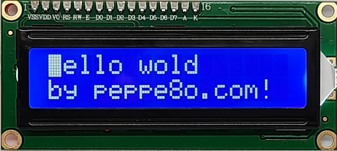
Test 3: Move the Cursor to Home
This test will show you the following command:
- lcd.home(): move the cursor to the first row and first column
Please download the following test script:
wget https://peppe8o.com/download/python/lcd/i2c-lcd-test-03-home.pyThe main part of the code will add the lcd.home() command after printing the message:
  lcd.message = "Hello wold"
  lcd.cursor_position(0,1)
  lcd.message = "by peppe8o.com!"
  lcd.home()
  lcd.blink = True
Please run the code with the following command:
python3 i2c-lcd-test-03-home.pyThe result is shown in the following picture:
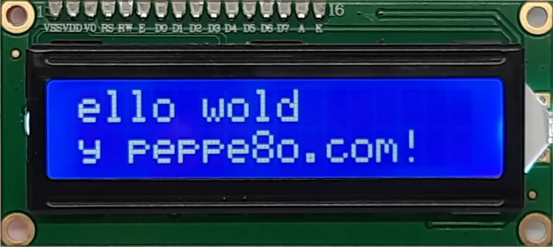
Test 4: Move The Printed text
This test will show you the following command:
- lcd.move_left(): shifts the printed text 1 column to left
A similar command available to your LCD Display is the following:
- move_right(): shifts the printed text 1 column to right
To test this command, please download the following script:
wget https://peppe8o.com/download/python/lcd/i2c-lcd-test-04-move-left.pyHere you will find the move_left() command after printing out text:
  lcd.message = "Hello wold"
  lcd.cursor_position(0,1)
  lcd.message = "by peppe8o.com!"
  lcd.move_left()
Run the script with the following command:
python3 i2c-lcd-test-04-move-left.pyThe result follows:
Test 5: Change the Text Direction
This test will show you the following command:
- lcd.text_direction: changes the text direction. Available values are lcd.RIGHT_TO_LEFT and lcd.LEFT_TO_RIGHT
Please download the test script with the following>
wget https://peppe8o.com/download/python/lcd/i2c-lcd-test-05-text-direction.pyThe main part of the program is the following:
  lcd.message = "Hello wold"
  lcd.cursor_position(0,1)
  lcd.text_direction = lcd.RIGHT_TO_LEFT
  lcd.message = "by peppe8o.com!"
Run the code with the following command:
python3 i2c-lcd-test-05-text-direction.pyAnd the result follows:
Test 6: Create Custom Characters
The last test in this tutorial will show you how to create custom characters. As said at the beginning of this tutorial, the LCD Display allows us to create custom characters and save them into 8 memory positions (with the ID from 0 to 7).
Our new command is:
- lcd.create_char(mem_id, char_array) [where “mem_id” is an integer number between 0 and 7, and “char_array” is a list object with hexadecimal values]: this command allows you to create and save custom characters in the display memory
Before starting to see the code, please note that every “text box” of our display is a combination of 5 x 8 light points. By using the https://www.quinapalus.com/hd44780udg.html web page, once you are sure that you selected the 5 by 8 character selection, you can compose any image clicking one by one the single points or choosing the available templates. It will return the related value in hex:
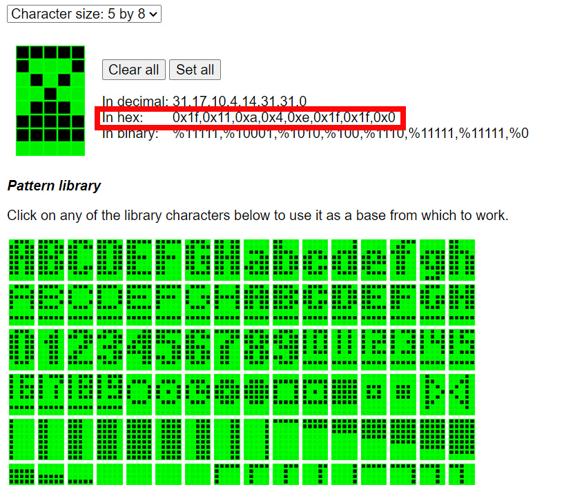
So, for the selected hourglass image the related array to use for displaying in the LCD is [0x1f,0x11,0xa,0x4,0xe,0x1f,0x1f,0x0].
Please download the following example script:
wget https://peppe8o.com/download/python/lcd/i2c-lcd-test-06-custom.pyIn the main program, we define the arrays with a few custom characters:
right_arrow = [0x0,0x8,0xc,0xe,0xc,0x8,0x0,0x0]
hourglass_01 = [0x1f,0x11,0xa,0x4,0xa,0x11,0x1f,0x0]
hourglass_02 = [0x1f,0x11,0xa,0x4,0xa,0x1f,0x1f,0x0]
hourglass_03 = [0x1f,0x11,0xa,0x4,0xe,0x1f,0x1f,0x0]
You can define as many characters arrays as you want, but you can save up to 8 custom images at time in the display memory.
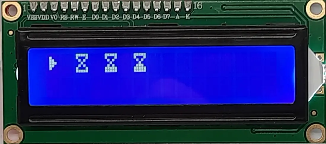
Once you have the arrays, you can save them in the display memory position with the create_char command. In this example, I will save 4 characters:
lcd.create_char(0, right_arrow)
lcd.create_char(1, hourglass_01)
lcd.create_char(2, hourglass_02)
lcd.create_char(3, hourglass_03)
Finally, you can show them by using the lcd.message command with the “\x” escape string, followed by the memory position of your custom character. The example in my script shows you how to print all of my custom characters:
lcd.message = "\x00 \x01 \x02 \x03 "Please run the script with the following command:
python3 i2c-lcd-test-06-custom.pyAnd you will have the following result:
What’s Next
Want to know more about cool projects to do with Raspberry PI computer boards? In this case, the right resource for you is my Raspberry PI tutorials pages.
Enjoy the 1602 LCD with Raspberry PI!

Open source and Raspberry PI lover, writes tutorials for beginners since 2019. He's an ICT expert, with a strong experience in supporting medium to big companies and public administrations to manage their ICT infrastructures. He's supporting the Italian public administration in digital transformation projects.
![]()
![]()
![]()
![]()
![]()
![]()
![]()