
Last Updated on 19th June 2024 by peppe8o
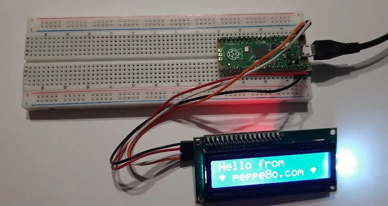
In this tutorial I’m going to show you how to connect and use an I2C LCD display to Raspberry PI Pico.
Adding a display to Raspberry PI Pico allows getting real time information from connected devices without using a computer from USB port. I2C LCD displays (with PCF8574 backpack) are one of best solution to keep wiring simple
The I2C LCD Display
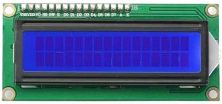
I2C LCD displays are common LCD displays, usually composed of 16 columns x 2 rows blocks, but also different configurations can be found. Differently from simple LCD displays, they include a small panel soldered in its backside, including chips able to reduce their connection wires. The I2C LCD display usually has a PCF8574 chip, which is a device able to convert I2C serial communication into parallel connections.
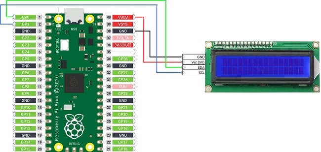
To connect an I2C LCD Display with your Raspberry PI Pico, you just need to wire the Vcc and GND PINs from display to VSYS and a GND PINs of RPI Pico, then SDA and SCL PINs from the I2C Display to a couple of SDA and SCL PINs from Raspberry PI Pico, belonging to the same I2C bus, as shown in the picture on the following wiring diagram chapter.
A working solution uses the dhylands-python_lcd module including a generic API to interface to LCD displays. But this class implements commands to be sent to the LCD without caring about how to send them. The reason is that there are many different backpacks and every solution can be implemented in many different ways. The ones created with a PCF8574 use I2C as communication protocol, in this case, you need a sort of driver able to send commands via I2C. This function is implemented with a second module from T-622 user, also available from T-622 GitHub page.
What We Need
As usual, I suggest adding from now to your favourite e-commerce shopping cart all the needed hardware, so that at the end you will be able to evaluate overall costs and decide if to continue with the project or remove them from the shopping cart. So, hardware will be only:
- A common computer (maybe with Windows, Linux, or Mac). It can also be a Raspberry PI Computer board
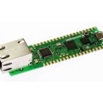
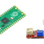
- Raspberry PI Pico microcontroller (with a common micro USB cable)
- I2C LCD Display (with PCF8574 backpack)
- breadboard
- dupont wirings
Check hardware prices with following links:


Wiring Diagram
Please find in following picture my wiring diagram:
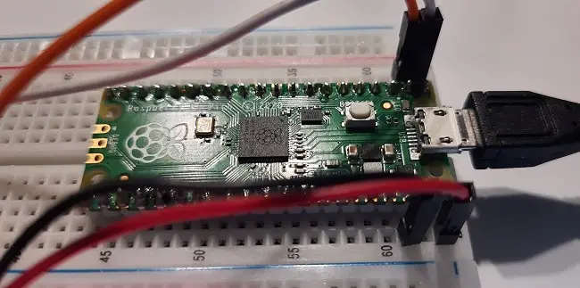
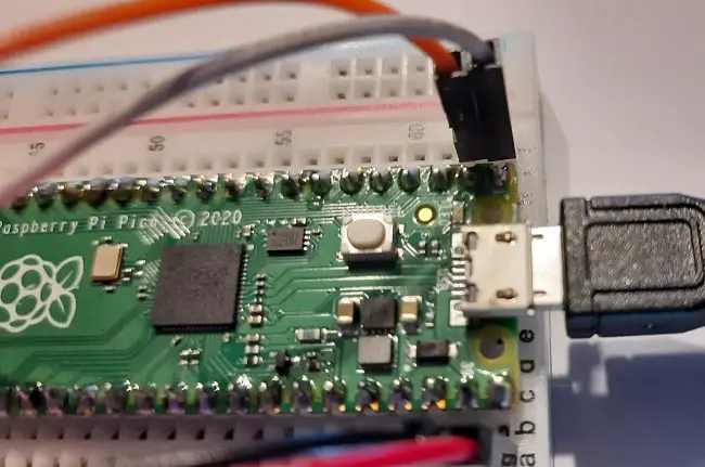
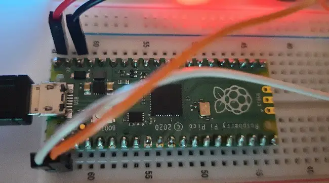
Following pictures give some additional details on my cabling:
Step-by-Step Procedure
Prepare cabling according to the previous paragraph. Connect RPI Pico to Thonny (you can refer to my tutorial about First steps with Raspberry PI Pico).
Download required micropython modules:
- the LCD_API: https://raw.githubusercontent.com/dhylands/python_lcd/master/lcd/lcd_api.py
- the I2C LCD: https://raw.githubusercontent.com/T-622/RPI-PICO-I2C-LCD/main/pico_i2c_lcd.py
You can also get them from my download area:
Download these files and save them in your Raspberry PI Pico root or under “lib” folder.
Before going into the usage explanation, you have to be sure that your LCD’s I2C address is correct. This is a unique address shared between I2C devices to make them able to talk on the same shared wire. This is usually a hexadecimal value and all devices connected to your RPI Pico can be scanned by copy-paste of the following code in your Thonny shell (you can copy all lines together):
import machine
sdaPIN=machine.Pin(0)
sclPIN=machine.Pin(1)
i2c=machine.I2C(0,sda=sdaPIN, scl=sclPIN, freq=400000)
devices = i2c.scan()
if len(devices) == 0:
 print("No i2c device !")
else:
 print('i2c devices found:',len(devices))
for device in devices:
 print("Hexa address: ",hex(device))
As I2C LCD with PCF8574 backpack use PCF8574 chip for I2C communication, you will probably get its default address (0x27). But if your project includes more PCF8574-based chips, then you will need to identify the LCD one between those that will be shown. In case of missing devices, please check your cabling.
Starting to use your LCD device, you can run a generic test with the T-622 test script, which I have pre-configured for 16×2 LCDs using I2C0 channel (ports GP0 and GP1 according to my wiring diagram). This modified script can be get from my download area (use the following link: i2c_lcd_test). Save this file in your Raspberry PI Pico root folder or in your computer and open it with Thonny IDE.
If your LCD display has a different I2C address, you will need to set it changing following line:
I2C_ADDR = 0x27If your LCD display has a different number of total columns or rows, you will need to set them changing following lines:
I2C_NUM_ROWS = 2
I2C_NUM_COLS = 16
At this point, you are ready to test your display. From Tonny IDE run the “i2c_lcd_test.py” file (F5) and you will start seeing some tests in a loop.
If you will see nothing, please check your cabling. Another common issue with I2C LCD display is getting a clean screen which is only powering on and off. This means that your connection is correct and everything is working, you have only to adjust your LCD contrast by rotating the screw positioned in your LCD backside, which controls a potentiometer managing contrast:
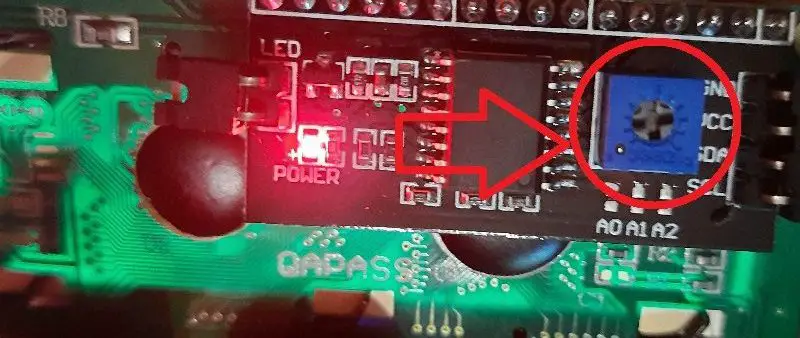
This should solve your issue.
Showing Special Characters
The LCD API used has a flexible feature allowing users to display also complex icons inside a single cell. Some special characters are already available and depend on your LCD ROM (Read Only Memory, space not visible to the user). You can use these chars with “lcd.putchar(chr())” function.
In your Thonny shell, paste following code (you can copy all lines together):
from machine import I2C
from lcd_api import LcdApi
from i2c_lcd import I2cLcd

I2C_ADDR     = 0x27
I2C_NUM_ROWS = 2
I2C_NUM_COLS = 16

i2c = I2C(0, sda=machine.Pin(0), scl=machine.Pin(1), freq=400000)
lcd = I2cLcd(i2c, I2C_ADDR, I2C_NUM_ROWS, I2C_NUM_COLS)
lcd.putchar(chr(247))
If you get a “π” char, then you have a Japanese ROM. If you get a “÷”, then you have an European ROM.
As reported from LCD API author, characters match ASCII characters in range 32-127 (0x20-0x7F) with a few exceptions:
- 0x5C is a Yen symbol instead of backslash
- 0x7E is a right arrow instead of tilde
- 0x7F is a left arrow instead of delete
Only the ASCII characters are common between the two ROMs 32-125 (0x20-0x7D). You can refer to the HD44780 datasheet for the table of characters.
Custom Icons
The first 8 characters (from 0 to 7) character-generator RAM. This means that you can define and design any icon you want to display by identifying pixels to be put on/off for each char block, made of 8 rows and 5 columns of pixels. Each row A good description of how to define a generic icon is explained in https://github.com/dhylands/python_lcd.
I’ve also prepared a simple MS Excel file that can help you designing your personal icon and generating related code to use in your script. You can download it from this link: bytearray code generator.
With this file, while you set to 1 or 0 (zero) the cells in the drawing zone, these cells will change color according to their value and the code will be generated. In this way, you will have an immediate preview of what you are drawing and related code to use:
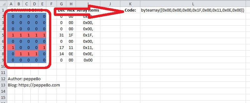
You can use the generated code with “lcd.custom_char()” command. An example usage is built in my pico_i2c_lcd script. Download and open it in your Thonny IDE.
This scripts starts importing required modules:
import machine
from machine import I2C
from lcd_api import LcdApi
from i2c_lcd import I2cLcd
Then common variables are set (please remember to set according to your device, if different from mine one):
I2C_ADDR     = 0x27
I2C_NUM_ROWS = 2
I2C_NUM_COLS = 16
The i2c instance is initialized and lcd object is initialized:
i2c = I2C(0, sda=machine.Pin(0), scl=machine.Pin(1), freq=400000)
lcd = I2cLcd(i2c, I2C_ADDR, I2C_NUM_ROWS, I2C_NUM_COLS)
Following part is where the custom icon is generated, using the code coming from my generator. This icon is associated to custom char (with id value going from 0 to 7):
heart = bytearray([0x00,0x0a,0x1f,0x1f,0x0e,0x04,0x00,0x00])
lcd.custom_char(0, heart)
Final line uses a concatenation (the “+” operator concatenates strings in MicroPython) of text strings and custom char to be printed on LCD display:
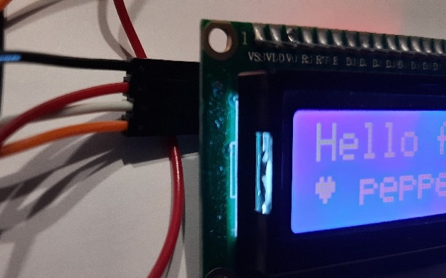
lcd.putstr("Hello from\n"+chr(0)+" peppe8o.com "+chr(0))And following result comes from script running:
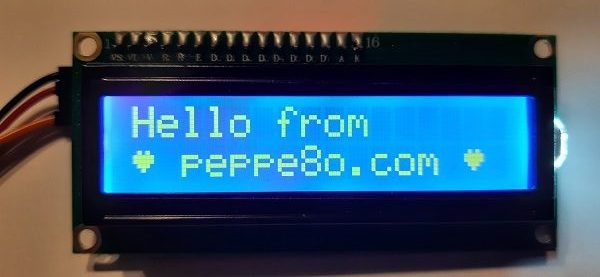
What’s Next
Interested to do more with your Raspberry PI Pico? Try to look at my Raspberry PI Pico tutorials for useful and funny projects!
Enjoy!

Open source and Raspberry PI lover, writes tutorials for beginners since 2019. He's an ICT expert, with a strong experience in supporting medium to big companies and public administrations to manage their ICT infrastructures. He's supporting the Italian public administration in digital transformation projects.
![]()
![]()
![]()
![]()
![]()
![]()
![]()
hello
I’m an old newbie…
I tried to find out how to download the lcd_api and i2c_lcd modules in the /lib folder.
Could not find. How can I do this ?
Thanks by advance
Jacques
Hi Jacques,
you can refer my Adding external modules to micropython with Raspberry PI Pico/ guide to find out how to create a lib folder in your Pico, so adding files with Thonny “Files > Save As” menu command. Please let me know if more help is needed
Oh, many thanks for this quick reply. I’ll try that…tomorrow…it’s already 8.00 pm here !
This morning (July 12th), I’m happy : it works !
I’m an old man an a newbie in micropython (and Thonny). Just a few days of experience and I do not master this technique.
I’m trying to maintain my neurons awake and use Arduino C++ since 2-3 years.
I’m trying to find out if I can program a full epidemiological model in a microcontroller and this is why I switched over to micropython and RP2040.
Thanks again, Giuseppe.
Hi Giuseppe
I’m trying to send you a mail with your giuseppe@peppe80.com address
Adresse is rejected by my operator.
Can you send me your mail ?
Mine is jacques.blanchart@wanadoo.fr
Jacques
This comment doesn’t need to be published of course
Hi Jacques,
this blog is peppe8o and not peppe80 (le last char is an ou, not a zero). So my email address is giuseppe@peppe8o.com
Excellent postings Giuseppe!! Very clear instructions. Many thanks.
Thank you for your feedback!
Could it be that lcd_putstr always starts from position 0,0 ?
Using lcd.move_to does not seem to change the position
def putchar(self, char):
“””Writes the indicated character to the LCD at the current cursor
position, and advances the cursor by one position.
“””
Hi Ardo,
according to the library comments within the code, the lcd.move_to(0,1) shold move the cursor to the second line and then the lcd.putchar() should start writing from here, moving then the cursor by 1 char. I interpret the code like you. But in this period I don’t have the LCD with me to test and give you a feedback. Maybe you can ask the library owner if there’s something we are missing
I figured out the address and changed it on variable I2C_ADDR, the program runs fine on Thonny (no errors) but LCD keeps showing white blocks on Row 0, Row 1 is blank?
I use Grove 16×2 I2C LCD ( White on Blue, V2.0)
Hi Bart. Please, can you try changing the contrast? There should be a screw in the back of your LCD
Hi Peppe,
The Grove I2C 16×2 LCD doesn’t seem to have a screw (potentiometer) to change contrast? Is there I2C function available or only HW capable to change contrast?
Thanks
Bart
ok. What is the I2C address you get from the LCD?
I get 0x3E (62 DEC) from scan.
I use below code in Thonny and it doesn’t give any error message so the code works fine.
import machine
from machine import I2C
from lcd_api import LcdApi
from i2c_lcd import I2cLcd
# setup LCD object
I2C_ADDR = 0x3E
I2C_NUM_ROWS = 2
I2C_NUM_COLS = 16
i2c = I2C(0, sda=machine.Pin(0), scl=machine.Pin(1), freq=400000)
lcd = I2cLcd(i2c, I2C_ADDR, I2C_NUM_ROWS, I2C_NUM_COLS)
# creating custom icon
heart = bytearray([0x00,0x0a,0x1f,0x1f,0x0e,0x04,0x00,0x00])
lcd.custom_char(0, heart)
# Main program
lcd.putstr(“Hello from\n”+chr(0)+” peppe80 “+chr(0))
I suspect that it has a different chip (as the i2c address is different from that I tested. Would you like to try the following, please:
https://github.com/Bucknalla/micropython-i2c-lcd
controller = AIP31068L&AIP31065 or Equivalence according to Datasheet.
I tried from Bucknalla but get attribute error : Object ‘I2C’ has no attribute ‘MASTER’
At this point it’s really hard for me to help from remote. Is the LCD new? Or you already used it with another controller? I can’t even exclude that the LCD may also be defective and you could ask the vendor to give you help or a new one
Have you ever tried the code with a Waveshare LCD1602?
The code appears to run correctly but nothing appears on the screen. I can write successfully with the Waveshare RGB1602.py library but nothing else.
Hi Neil,
if you use a Waveshare LCD, there’s a chanche that your display is an RGB type instead of the one used in this tutorial. In this case, I suggest to try their test procedure, as explained in https://www.waveshare.com/wiki/Template:LCD1602_RGB_Module_Guides_for_Pico