Last Updated on 27th February 2026 by peppe8o
In this article, I’m going to explain the Raspberry PI pinout schema for computer boards. This is useful when we plan to interface the Raspberry PI with external electronic parts like motors and sensors.
What Are Raspberry PI GPIO
GPIOs (General Purpose Input/Output) are physical pins that you can use to acquire states or information from external devices. GPIO can also control external devices.
From the electrical point of view, each Raspberry PI has several PINS used for providing power to external sensors/motors. You can configure all other pins both to receive or provide a tension value, which can be 0V (low) or 3,3 V (high). You can manage these settings via Python or C/C++ programs.
Get the GPIO Map from GPIOZero
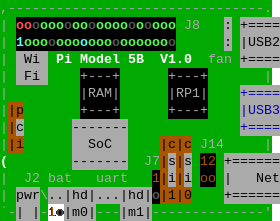
With Python, it is also possible to map in your terminal the pinout configuration by using the GPIOZero library (already available both in Raspberry PI OS Desktop and Raspberry PI OS Lite). From your Raspberry PI terminal, please use the following command to have a graphical map:
pinoutThis will give you something like a graphical view of your board. You will get in your terminal a picture like the following (this is from a Raspberry PI 5 Model B, but you will see your model):
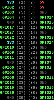
The same command will also show you the physical and BCM (Broadcom) numbering for each GPIO PIN:
Difference Between Physical and BCM (Broadcom) Numbering in Raspberry PI Pinout
On Raspberry PI boards, there are two main ways to identify header pins: Physical numbering and BCM numbering. Confusing the numbering between the first and the second is one of the most common errors for beginners, leading to bugs, dead sensors, or – in the worst cases – a burnt board.
- The Physical numbering (often called “BOARD”) simply counts the pins along the 40‑pin header. It is a purely positional scheme and doesn’t care what function each pin provides. In the previous screenshot from the
pinoutexport it matches the numbers in grey. - The BCM (Broadcom) numbering, on the other hand, refers to the internal Broadcom SoC’s GPIO line numbers (GPIO2, GPIO3, GPIO4, etc.), which are how the chip itself identifies signals. In the previous screenshot from the
pinoutexport it matches the GPIOxx, GND, 5V, and 3V3 labels.
Common pinout references usually show both numbers side‑by‑side.
Software libraries usually enable you to select one scheme or the other. The GPIOZero library (which is installed by default in Raspberry PI OS) uses a pure number to use the BCM schema, or a “BOARDxx” to select the physical schema. For example a LED connected to the physical PIN 11 / BCM GPIO17 can be initialised in both the following alternative ways:
- BCM ->
led = LED(17) - Physical ->
led = LED("BOARD11")
Usually, developers prefer the BCM schema, but you can freely use the one you prefer.
The 40-pin Raspberry PI Pinout
Some of the very early “Raspberry PI 1” computer boards were equipped with a limited “26-pin” header.
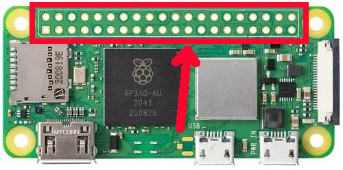
Soon it was expanded to the classic “40-pin” header we can see in all of the Raspberry PI boards. In some limited cases, we can see an “unpopulated” footprint (some of the Raspberry PI Zero versions), where you can solder a header to get your PINs. It appears to you as a number of holes in the board:
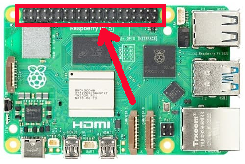
All the other models (including the Zero WH) give you the PINs already populated with a header where you can plug the Dupont wiring required to connect external sensors or motors:
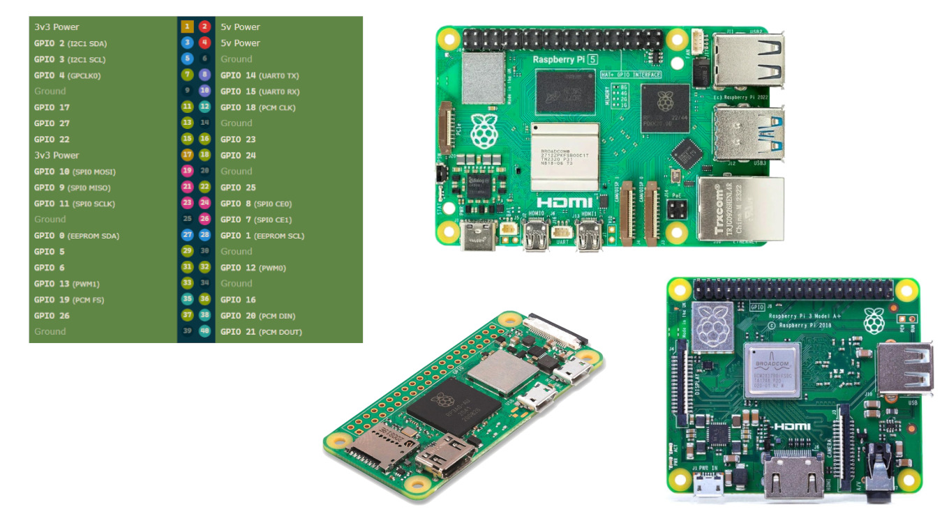
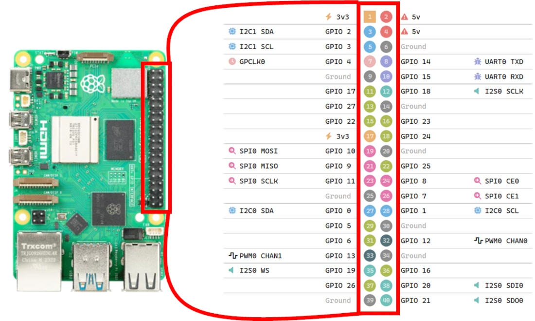
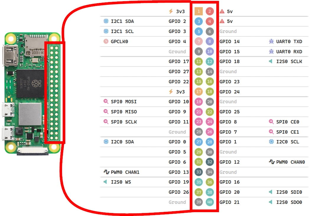
Raspberry PI Pinout Schema
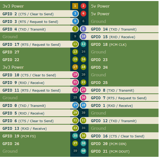
The following picture shows you the basic schema for Raspberry PI pinout with a model B board:
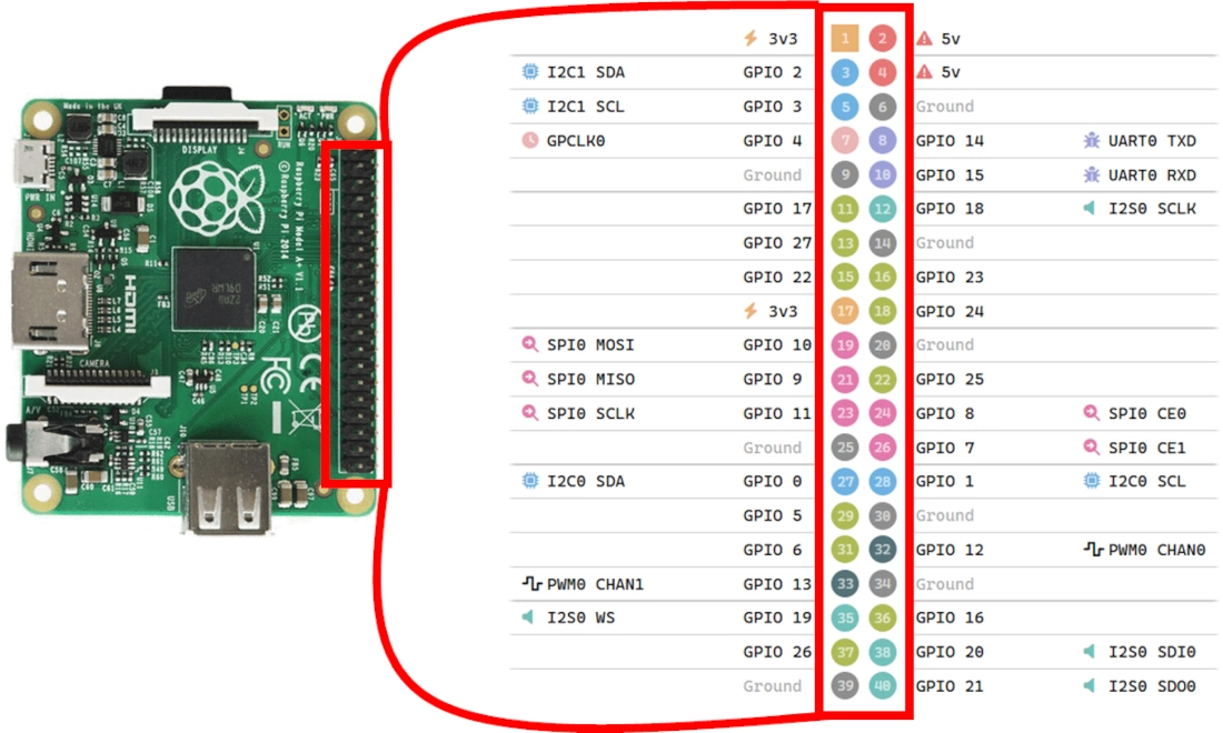
With other Raspberry PI models, the pinout schema keeps its schema, while the right position may confuse beginners. The following pictures, respectively showing Model A and Zero, should remove any doubts:
PIN Functions
All of the PINs have specialised functions, depending on how you use them.
A great visual mapping is available at the https://pinout.xyz/ website, where you can find interactive views of the pinout. In this chapter, I will summarise the main grouping by keeping the images from there.
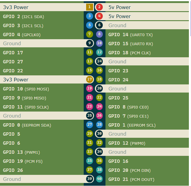
Power PINs
The most important PINs are those where you can connect the ground level with sensors/motors, as well as where you can give power to active devices.
The Raspberry PI boards offer you several Ground, 5V, and 3.3 Volt PINs as shown in the following picture:
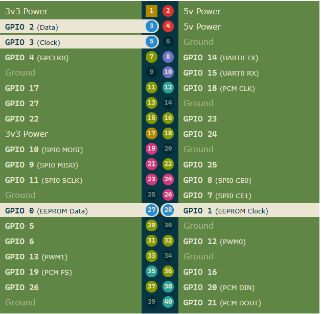
I2C PINs
I2C can be used to communicate with devices compatible with Inter-Integrated Circuit (a low-speed two-wire serial protocol). This communication standard requires master-slave roles between the two parts. I2C has two connections: the data port (usually referred as SDA) and the clock (SCL). They work by sending data to and from the SDA connection, with the speed controlled via the SCL pin.
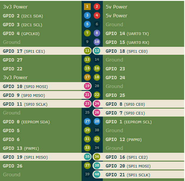
SPI PINs
SPI (Serial Peripheral Interface) is another protocol for Raspberry PI to communicate with devices in master-slave communication. You can use it for short-distance communications. The Raspberry PI pinout offers 2 SPI channels (0 and 1).
Data is synchronised using a clock (SCLK) from the master (usually the Raspberry PI) and the connected device. The data is sent from the PI to our SPI slave using the Master Out Slave In (MOSI) PIN. If the connected device needs to reply to our PI, then it will send data back using the Master In Slave Out (MISO) pin.
UART PINs
Commonly known as “Serial,” the UART (Universal Asynchronous Receiver / Transmitter) pins provide a console/terminal login for an alternative headless setup. TX and RX stand for transmission and reception.
Resources
Next Steps
If you are interested in more Raspberry PI projects (both with Lite and Desktop OS), take a look at my Raspberry PI Tutorials.
Enjoy!

Open source and Raspberry PI lover, writes tutorials for beginners since 2019. He's an ICT expert, with a strong experience in supporting medium to big companies and public administrations to manage their ICT infrastructures. He's supporting the Italian public administration in digital transformation projects.
![]()
![]()
![]()
![]()
![]()
![]()
![]()