
Last Updated on 15th March 2025 by peppe8o
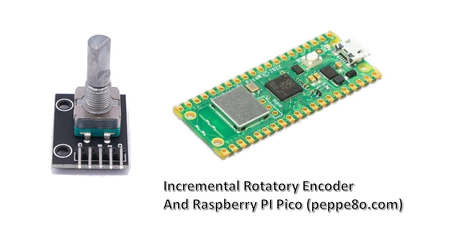
In this tutorial, I will show you how to connect and use an Incremental Rotary Encoder with a Raspberry PI Pico microcontroller. I will show you how to manage the connections and use MicroPython to control them.
Before starting, let’s see how Rotary Encoders work.
About Rotary Encoders
The most known models of this module are the KY-040 and Hw-040. They work in the same way.
This module is mainly composed of a shaft (with an integrated button that you can push) and it can measure the rotation of the shaft. You can use these modules with any microcontroller, such as the Pico and Arduino.
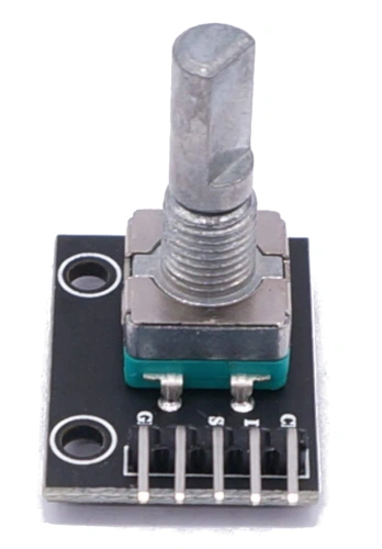
Differently from a Potentiometer, the knob of the rotary encoder can turn clockwise or counterclockwise an infinite number of times. The potentiometer requires analog ports, while the rotary encoders will work with digital connections.
There are 2 different kinds of rotary encoders: Incremental Encoders and Absolute Encoders. The Incremental Encoders will give you the measurement of how many steps the knob has been moved, while the Absolute Encoders (also known as Angle Encoder) will give you the exact position of the rotation angle. As you may suppose from the title of this article, here I will show you how to use the Incremental module.
How Rotary Encoders Work
The module has a central shaft rotating into specific position slots. You can feel these positions by gently moving the shaft in one of the 2 directions. The Rotary Encoder will count the number of positions clockwise or counterclockwise.
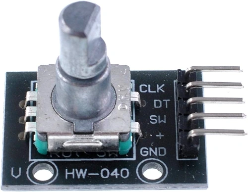
The Rotary Encoder pinout includes 5 PINs:
| PIN Label | Description |
|---|---|
| GND | Connected to the ground |
| + (or VCC) | Connected to the power supply |
| SW | Connected to the shaft button, active at low values |
| DT | Digital PIN detecting the rotation direction |
| CLK | Digital PIN detecting the rotation movement |
The sharp is connected to a small gear. The ground reference is connected to the shaft, while the CLK e DT are connected to 2 sensors detecting the gear motion at the gear boards. At the shaft/gear rotation, the 2 sensors change state. The direction is read from the module by checking which of the 2 sensors changed its state first. A great video showing how it works is the following:
What We Need
As usual, I suggest adding from now to your favourite e-commerce shopping cart all the needed hardware, so that at the end you will be able to evaluate overall costs and decide if to continue with the project or remove them from the shopping cart. So, hardware will be only:
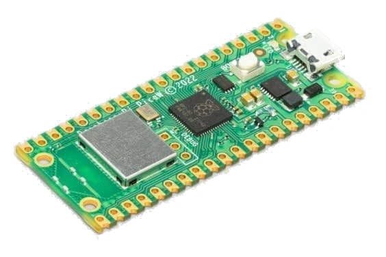
- Raspberry PI Pico microcontroller (with a common micro USB cable). I suggest buying the W version, as it includes WiFi connectivity.
- Dupont wirings
- Breadboard (optional)
- Incremental Rotary Encoder (like KY-040 or HW-040). I got mine from the Elecrow Pico Advanced kit.
Step-by-Step Procedure
Incremental Rotary Encoder and Raspberry PI Pico Wiring Diagram
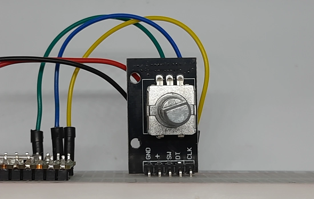
Please arrange the connections as shown in the following picture, according to the Raspberry PI Pico Pinout:
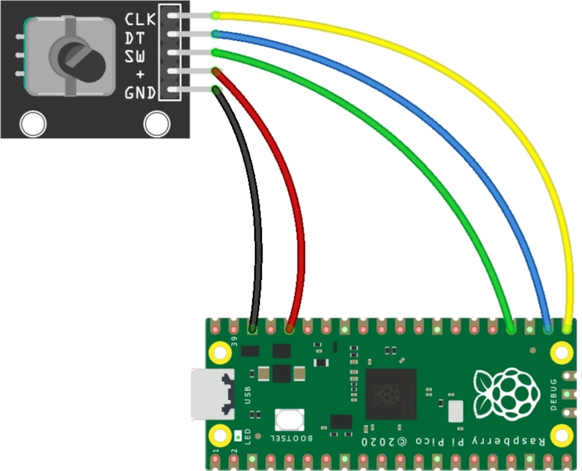
The following table will help you with the wiring:
| Raspberry PI Pico | Rotary Encoder |
|---|---|
| GND | GND |
| 3V3 | + |
| GP18 | SW |
| GP17 | DT |
| GP16 | CLK |
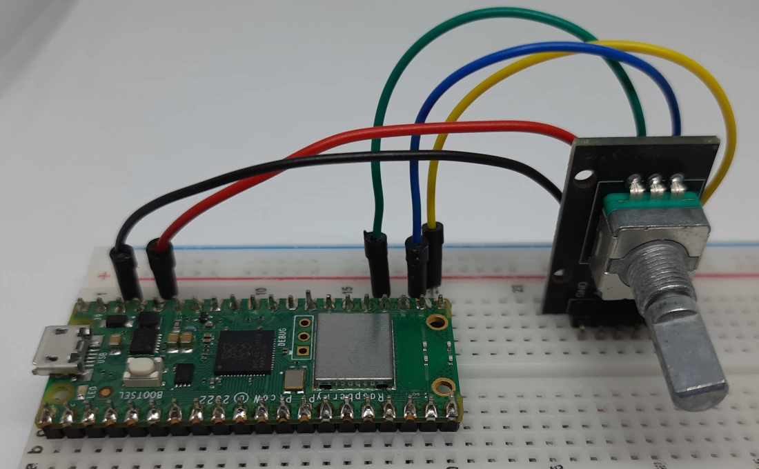
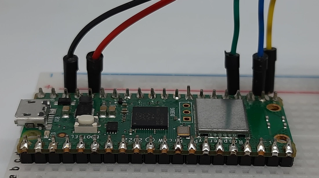
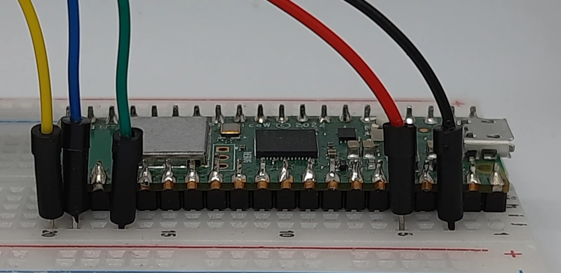
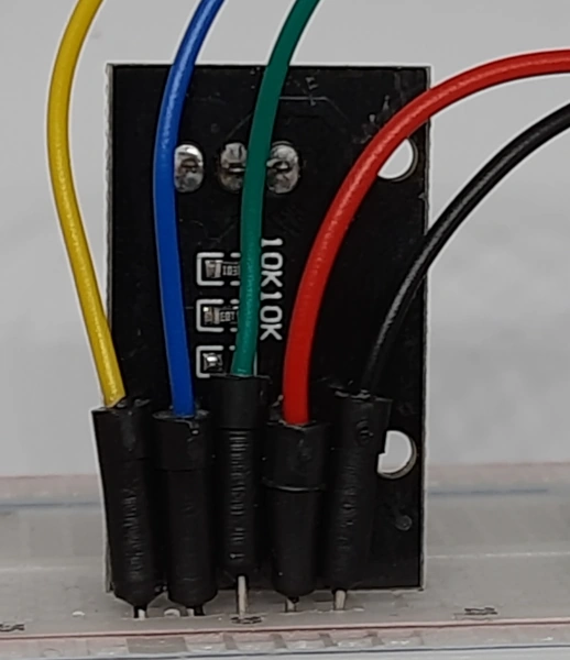
Please find below some pictures from my home lab:
Install MicroPython on Raspberry PI Pico
For this tutorial, I suggest you use Thonny IDE installed on your computer. This will make your work with Pico simpler.
Connect the Raspberry PI Pico to Thonny. For the first steps to install MicroPython, please refer to my tutorial about the First steps with Raspberry PI Pico.
Testing The Rotary Encoder Model
Sometimes, the theory may be different from practice… So, I found that my rotary encoder was working differently from the way I expected it to work.
For this reason, I prepared a small script giving you the output from your module. In this way, you should be able to get the encoder working even with different hardware. The script will allow you to check what are the signals coming from the clk and dt PINs at encoder rotations.
Please download the following MicroPython script on your PC:
Here’s the line-by-line explanation of the code.
In the beginning, we import the required library. We need only the Pin library:
from machine import PinThen we define the Raspberry PI Pico PINs where the CLK and DT are connected. At this stage, we don’t need to define the shaft button PIN (SW). Please change them if you used a different wiring schema:
clk_pin = 16
dt_pin = 17
The following lines will initialize the MicroPython PIN objects related to the same PINs:
clk_pin = Pin(clk_pin, Pin.IN, Pin.PULL_DOWN)
dt_pin = Pin(dt_pin, Pin.IN, Pin.PULL_DOWN)
Now, we start to get the values read from the Raspberry PI Pico from these PINs. We’ll also store these values in the “clk_val_prev” and “dt_val_prev” variables so that at any time we can compare the current readings with the previous ones:
clk_val_prev = clk_pin.value()
dt_val_prev = dt_pin.value()
The main program consists of a “while” loop. At each loop, it checks the CLK and DT values:
while True:
    clk_val = clk_pin.value()
    dt_val = dt_pin.value()
If one of these values differs from the previous reading, we’ll print both the CLK and DT values in the Thonny shell:
    if clk_val!=clk_val_prev or dt_val!=dt_val_prev:
        print(clk_val,", ",dt_val)
Finally, we store the new values in our “_prev” variables:
    clk_val_prev = clk_val
    dt_val_prev = dt_val
Get ClockWise and CounterClockWise Values
Now, you can run this script in your Thonny. As the script starts, please gently rotate the shaft for only 1 step ClockWise. This will provide in your Thonny shell a number of readings of the 2 PINs (CLK and DT). There should be 4 readings, similarly to the following:
>>> %Run -c $EDITOR_CONTENT
1 ,  0
0 ,  0
0 ,  1
1 ,  1
Please note that your values could differ from mine. Stop the script and run the test again for 1 or 2 times. You should always get the same results. Not it in an external notepad file, by adding them into a simple array. You should note them as “cw_path”. In my case, my notepad note is the following:
cw_path = [[1, 0], [0, 0], [0, 1], [1, 1]]This is the sequence which will identify a ClockWise rotation.
In the same way, please start the script again and make a single-step rotation CounterClockWise. You should get again 4 readings, these are mine:
>>> %Run -c $EDITOR_CONTENT
0 ,  1
0 ,  0
1 ,  0
1 ,  1
Again, re-test it by stopping the script and running it again for 1 or 2 times. Note this sequence as ccw_path in your notepad file. Mine one is:
ccw_path = [[0, 1], [0, 0], [1, 0], [1, 1]]Get the Incremental Rotary Encoder Script for Raspberry PI Pico
This script will implement a simple counter of the rotation steps, by increasing the counter when rotating the shaft clockwise and decreasing the counter in the opposite direction. The shaft button will reset the counter to 0.
Now, please download the following script from my download area:
The following paragraphs will explain this code line by line.
Again, at the begin we import the Pin library:
from machine import PinThe script uses again variables to define the GP number of your wiring connections. Here we also identify the SW PIN. Change it if you used a different wiring schema:
clk_pin = 16
dt_pin = 17
sw_pin = 18
As in the previous script, we initialize the PIN objects. Please note that the SW has a pull-up configuration, as when pressed it forces the output to low (similarly to Switch Buttons):
clk_pin = Pin(clk_pin, Pin.IN, Pin.PULL_DOWN)
dt_pin = Pin(dt_pin, Pin.IN, Pin.PULL_DOWN)
sw_pin = Pin(sw_pin, Pin.IN, Pin.PULL_UP)
Now, we initialize a “rot_log” list object. This will store the latest values read from the CLK and DT PINs. You can initialize it with any values:
rot_log=[[1, 1]]Then, the clockwise and counterclockwise paths come into play. Please take the values stored in your notepad file and put them here if you get different values:
cw_path = [[1, 0], [0, 0], [0, 1], [1, 1]]
ccw_path = [[0, 1], [0, 0], [1, 0], [1, 1]]
We also initialize our counter variable to 0:
counter = 0The first custom function is the “button_pressed()“. It configures the actions to be done when the shaft is pressed. In my case, it will simply set the counter variable to 0 and print the related message. Please note the global definition of the counter variable: it is important to allow the function to change the value of a variable which is out of the function:
def button_pressed(chn):
    global counter
    counter = 0
    print("Reset counter. New value: ",counter)
    return
Another important function is the “rotation_detected()” function. This executes the actions required when a rotation is detected. In our case, it will increase or decrease the counter when the program gets a matching from the latest CLK and DT values compared with the cw_path or ccw_path. At the beginning of this function, we define some variables required to keep the count also outside of the function:
def rotation_detected(chn):
    global last_log
    global rot_log
    global cw_path
    global ccw_path
    global counter
The “last_log” variable stores the latest reading from the CLK and DT PINs:
last_log = [clk_pin.value(), dt_pin.value()]If this reading differs from the latest values stored in our rot_log list, this means that the shaft is rotating. This is detected with the following line:
if last_log != rot_log[len(rot_log)-1]:In this case, the script appends the last_log values to the rot_log.
Then it reduces the length of the list object to the same length as the cw_path variable:
        rot_log.append(last_log)
        rot_log=rot_log[-len(cw_path):]
At this point, detecting if we get a clockwise or counterclockwise rotation is really simple: we just need to compare the rot_log with the 2 saved paths. In case of clockwise rotation, the script will increase the counter of 1 and print the related value. In the other direction, it will reduce the counter of 1 and print the related value:
        if rot_log == cw_path:
            counter += 1
            print(counter)
        if rot_log == ccw_path:
            counter -= 1
            print(counter)
The final “return True” closes this custom function without any additional operation:
return TrueThe following 3 lines are interesting. Differently from many rotary encoder scripts running on the web, I prefer to detect the shaft rotations and pressure with interrupt handlers. They allow us to automatically detect PINs changes and run the related custom functions. The SW handler will run the “button_pressed” function at the detection of a low value (Pin.IRQ_FALLING) for this input, while the CLK and DT handlers will run the “rotation_detected” function both on low-value detection (Pin.IRQ_FALLING) and high-value detection (Pin.IRQ_RISING):
sw_pin.irq(trigger=Pin.IRQ_FALLING,handler=button_pressed)
clk_pin.irq(trigger=Pin.IRQ_RISING | Pin.IRQ_FALLING, handler=rotation_detected)
dt_pin.irq(trigger=Pin.IRQ_RISING | Pin.IRQ_FALLING, handler=rotation_detected)
With this done, the main loop can include any other job (even a simply pass function which does nothing), as the print statements are already included in the related functions:
while True:
    pass
Test the Incremental Rotary Encoder with Raspberry PI Pico
At this point, you can run the “ky040_pico” script in your Thonny IDE to test it. You will get the counter values while rotating the shaft, as well as you will see the counter reset when pressing the shaft button, similarly to the following:
>>> %Run -c $EDITOR_CONTENT
1
2
3
4
5
6
5
4
3
2
1
0
-1
0
1
2
3
4
Reset counter. New value:  0
-1
-2
-3
-4
-5
What’s Next
Interested in doing more with your Raspberry PI Pico? Try to look at my Raspberry PI Pico tutorials for useful and funny projects!
Enjoy!

Open source and Raspberry PI lover, writes tutorials for beginners since 2019. He's an ICT expert, with a strong experience in supporting medium to big companies and public administrations to manage their ICT infrastructures. He's supporting the Italian public administration in digital transformation projects.
![]()
![]()
![]()
![]()
![]()
![]()
![]()