
Last Updated on 4th June 2024 by peppe8o
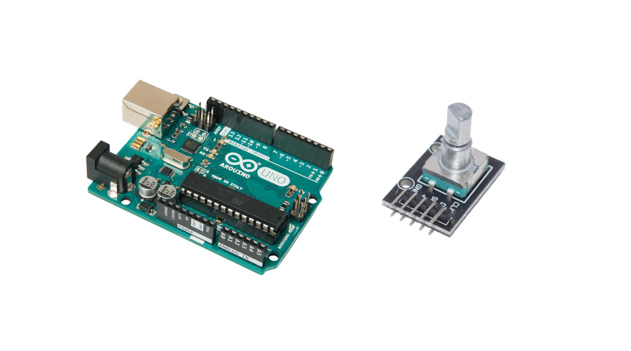
In this tutorial, we’ll interface a rotary encoder (KY-040) with Arduino Uno including code, connection diagram and component list.
To make set clock time and count increase with rotation probe, rotatory encoder ky-040 with Arduino is still best to use
The KY-040 Rotatory Encoder
The rotatory encoder is an instrument with which rotation senses and measures in a clockwise and anticlockwise direction. The first question that comes into mind is how a rotation measures? Well, the answer is given in the passages to follow. Using an encoder the rotation or angular position converts into an output signal which determines the direction and count of the rotation so the encoder is basically a position sensor. Machines, printers, etc. are the main application areas for encoders because of their ability to be precise and have fine digital control.
Types of Encoders
There are two types of rotary encoders: absolute encoders and incremental encoders. Absolute encoders provide the exact measure of rotation of the knob in degrees whereas the incremental encoders give the count of the knob in the clockwise or anticlockwise direction. The rotary encoder discussed here is of incremental type.
A slotted disk is present inside the rotary encoder which is ground by a pin name C. Two contact points A and B are also present. Depending on the rotation in which the knob rotates the contact points A and B come in contact with common point C in a particular order that determines rotation. When point A and B come in contact with a common point C, a signal produces the output. The signal produced by A is out of phase by 90 degrees to the signal produced by contact point B.
Clockwise/ Counterclockwise Rotation Determination
In case of rotation of the knob in a clockwise direction, pin A connects first, and pin B connects after that. Whereas for the rotation in counterclockwise direction pin B comes in contact prior to pin B. Using the signal changes that appear when a pin connects or disconnects from the ground, we determine in which direction the knob rotates:
- If B! =A, the knob rotates clockwise.
- If B=A, then the knob has turned anticlockwise.
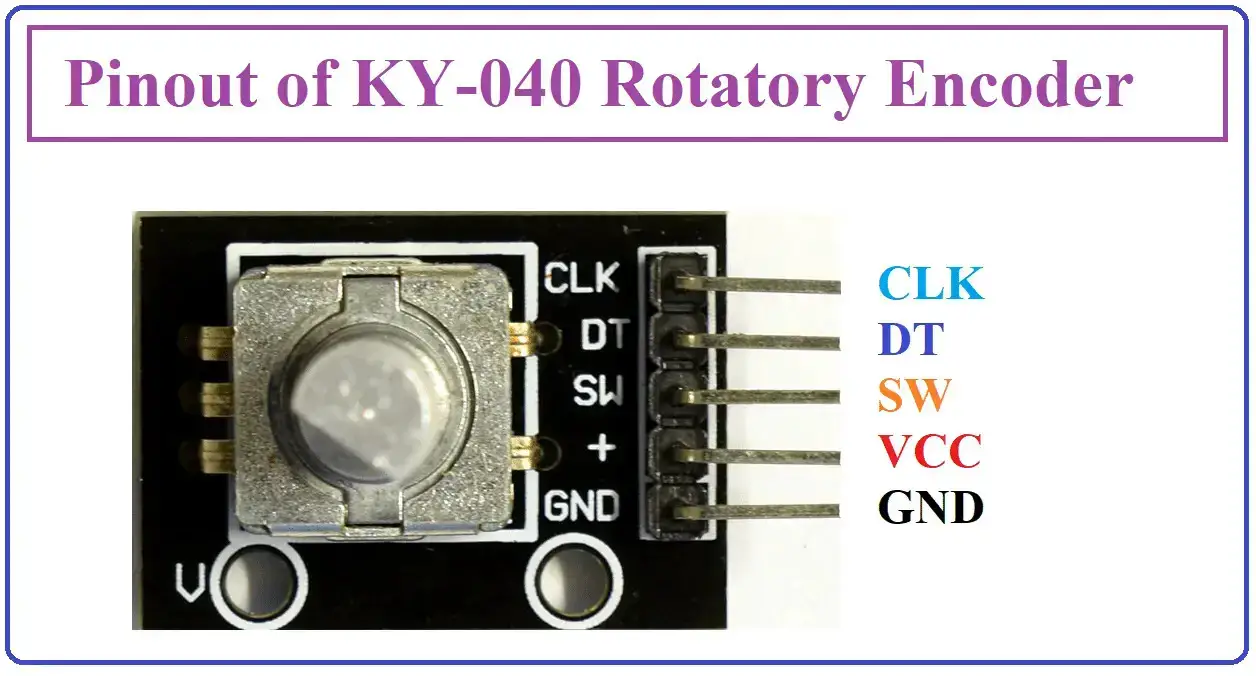
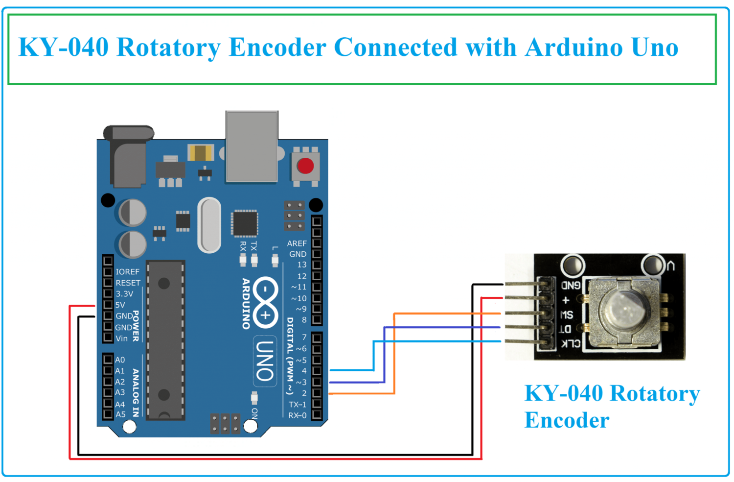
KY-040 Rotatory Encoder Pinout
- GND is the pin where ground connects.
- VCC is power pin to power up the encoder. This connects to 3.3 volt or 5 volt pin on Arduino Uno.
- SW is the active low push button output switch. When the knob pushs, the voltage goes low.
- DT (OUTPUT B) is the output pin where the signal lags the Clock (CLK) pin by 90 degree phase shift. This output is used to determine the direction of rotation of the knob.
- CLK (OUTPUT A) is the pulse or clock output. This pin completes one cycle that is it goes from HIGH to LOW for every click in either direction.
There are three pins on the sensor 1)Vcc 2) Ground 3) Out. The IR Sensor is a module consisting of three pins namely VCC, GND, and OUT. VCC is a power pin where 5 volts from the microcontroller is provided. GND pin of IR sensor connects with the ground pin of Arduino. OUT pin connects to any digital pins.
| Sr. | IR Sensor pin | Arduino Uno Pin |
| 1 | GND pin | GND pin of Arduino |
| 2 | VCC pin | 5V of Arduino Uno |
| 3 | SW pin | Pin 2 or any other digital pin of Arduino Uno |
| 4 | DT pin | Pin 3 or any other digital pin of Arduino Uno |
| 5 | CLK pin | Pin 4 or any other digital pin of Arduino Uno |
What We Need
As usual, I suggest adding from now to your favourite e-commerce shopping cart all the needed hardware, so that at the end you will be able to evaluate overall costs and decide if to continue with the project or remove them from the shopping cart. So, hardware will be only:
Check hardware prices with the following links:


Step-by-Step Procedure
Wiring Diagram
There are 5 pins for rotatory encoder ky-040. Starting from the left side, pin 1 is GND which has to be connected with GND. Pin 2 is a VCC that connects to the +5V of Arduino. Pin 3 is the SW wire to Arduino pin 2, Pin 4 is D which should be connected to pin 3. The last is the CLK pin which connects to pin 4 of Arduino.
Code Explanation Step by Step
Connect your PC to Arduino and open Arduino IDE. For the very first steps, you can refer to Connecting Windows PC with Arduino tutorial. You can get the .ino code from my download area with the following link:
At the beginning of the code, these directives are used to define the pins for CLK, DT, and SW are defined as pin numbers 4,3, and 2 respectively.
These are the lines used to declare different variables. A counter variable stores the value of how many times the knob is rotated. “currentStateCLK” variable tells about the current state of the encoder. ”lastStateCLK” variable stores the last state of the clock. Comparing the current and last state variables, we can determine the rotation direction of the knob.
#define CLK 4
#define DT 3
#define SW 2
int counter = 0;
int currentStateCLK;
int lastStateCLK;
String currentDir = "";
unsigned long lastButtonPress = 0;
These lines declare CLK, DT, and SW pins as inputs. The clock pin of the encoder is read and the value is stored in the variable named lastStateCLK.
void setup() {
  Serial.begin(9600);  // Setup Serial Monitor
  pinMode(CLK, INPUT);   // Set encoder pins as inputs
  pinMode(DT, INPUT);
  pinMode(SW, INPUT_PULLUP);
  lastStateCLK = digitalRead(CLK);  // Read the initial state of CLK
}
Then loop function executes. The setup function executes for just one time whereas the loop executes continuously.
At the beginning of the loop function, the clock pin is read and stored in the current state variable. If the value of the DT pin is not equal to the current clock state, then the counter variable decrements and it means that the rotation of the knob is in a counter-clockwise direction.
Otherwise, the counter increments and direction is clockwise so in string “CW” is stored to print on the serial monitor.
void loop() {
  currentStateCLK = digitalRead(CLK);  // Read the current state of CLK
  if (currentStateCLK != lastStateCLK  && currentStateCLK == 1) {
    if (digitalRead(DT) != currentStateCLK) {
      counter --;
      currentDir = "CCW";
    } else {
      counter ++;
      currentDir = "CW";
    }
    Serial.print("Direction: ");
    Serial.print(currentDir);
    Serial.print(" | Counter: ");
    Serial.println(counter);
  }
  lastStateCLK = currentStateCLK;
The button (knob) is checked whether pressed. If the variable is low, it means that the button has been pressed. This condition checks if a time of more than 50 milliseconds has passed then it should be printed the notice “Button pressed!”.
int btnState = digitalRead(SW);
  if (btnState == LOW) {
    if (millis() - lastButtonPress > 50) {
      Serial.println("Button pressed!");
    }
    lastButtonPress = millis();
  }
  delay(1);
}
Results
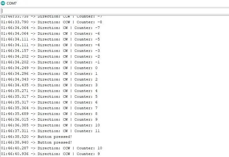
The results of the rotatory encoder are presented. When the knob is rotated in a clockwise direction the count decreases, while in an anticlockwise direction the count increases. When the button in the centre of the rotatory encoder is pressed, it displays the button.
What’s Next
Please find more tutorials on Arduino in peppe8o Arduino archives.
Enjoy!
Umar Jamil
For any queries and help for work, please contact me at:
Whatsapp: +92-346-661-7017
Email: umarjamil0007@gmail.com

I'm an Electronic Engineer, well-skilled to solve the issues of hardware and software. I do have laboratory which contains unlimited sensors and modules for testing the working. Also, I am experienced in Arduino programming, Android mobile application, microcontroller programming, IOTs and embedded projects. I provide services to control, realize the sensor data in the Mobile Application. For any queries and help for work Contact: Whatsapp:+92-346-661-7017 Email: umarjamil0007@gmail.com
![]()


