Last Updated on 19th May 2024 by peppe8o
This tutorial will show you how to use the SSD1306 with Raspberry PI: the OLED Display with a cheaper price to add cool output to your projects.
This tutorial is intended for Raspberry PI computer boards. If you want to use it with Raspberry PI Pico, please refer to my Add an OLED display to Raspberry PI Pico tutorial.
OLED Display Features
I already described the main features of OLED (Organic Light-Emitting Diode) displays in the referred tutorial for Raspberry PI Pico. So, here I will resume only the main concept:
- Required power: (usually) 0.04W
- range of operating temperatures: -40°C to 85°C
- Size: 128×64 pixels (0.96 inches), but also the 128×32 pixels (0.91 inches) is available from e-stores
- mono-color or bi-color screens (this tutorial will apply to both)
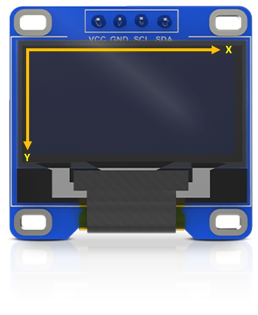
The pixels are indexed by a cartesian spacial reference, with the x-axis moving on the horizontal side and the y-axis moving on the vertical one. Both coordinates start from their 0 on top-left side of the screen:
SSD1306 OLED Pinout
The I2C version pins are defined according to the following table:
| PIN Label | Description |
| VCC | This PIN goes to the positive power source |
| GND | This PIN goes to the ground reference |
| SCL (or SCK) | This PIN is the clock reference for I2C communication |
| SDA | This PIN is used for data transferring according to I2C protocol |
What We Need
As usual, I suggest adding from now to your favourite e-commerce shopping cart all the needed hardware, so that at the end you will be able to evaluate overall costs and decide if to continue with the project or remove them from the shopping cart. So, hardware will be only:
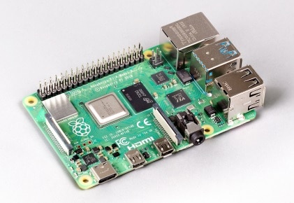
- Raspberry PI Computer Board (including proper power supply or using a smartphone micro USB charger with at least 3A)
- high speed micro SD card (at least 16 GB, at least class 10)
- I2C OLED display
Step-by-Step Procedure
Prepare the Wiring between SSD1306 and Raspberry PI
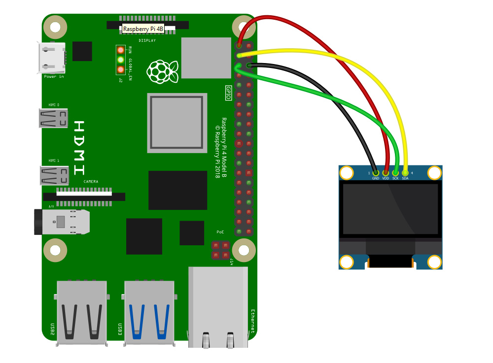
Please arrange the connections as described in this chapter, according to the Raspberry PI Pinout. The following table describes the GPIO to use:
| Raspberry PI | SSD1306 OLED |
|---|---|
| GND | GND |
| 3.3V | VDD |
| GPIO3/SCL (n.5) | SCK |
| GPIO2/SDA (n.3) | SDA |
The following picture shows you the wiring schema:
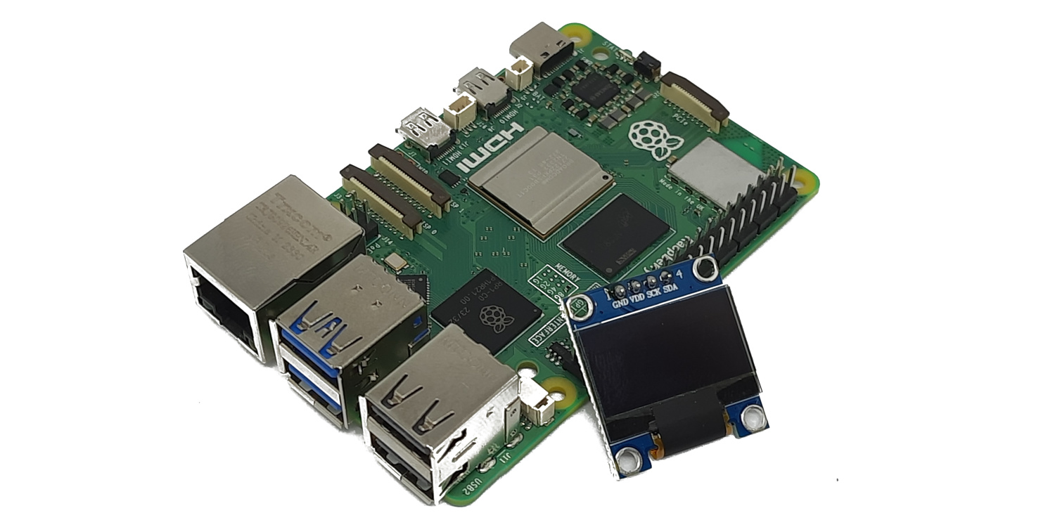
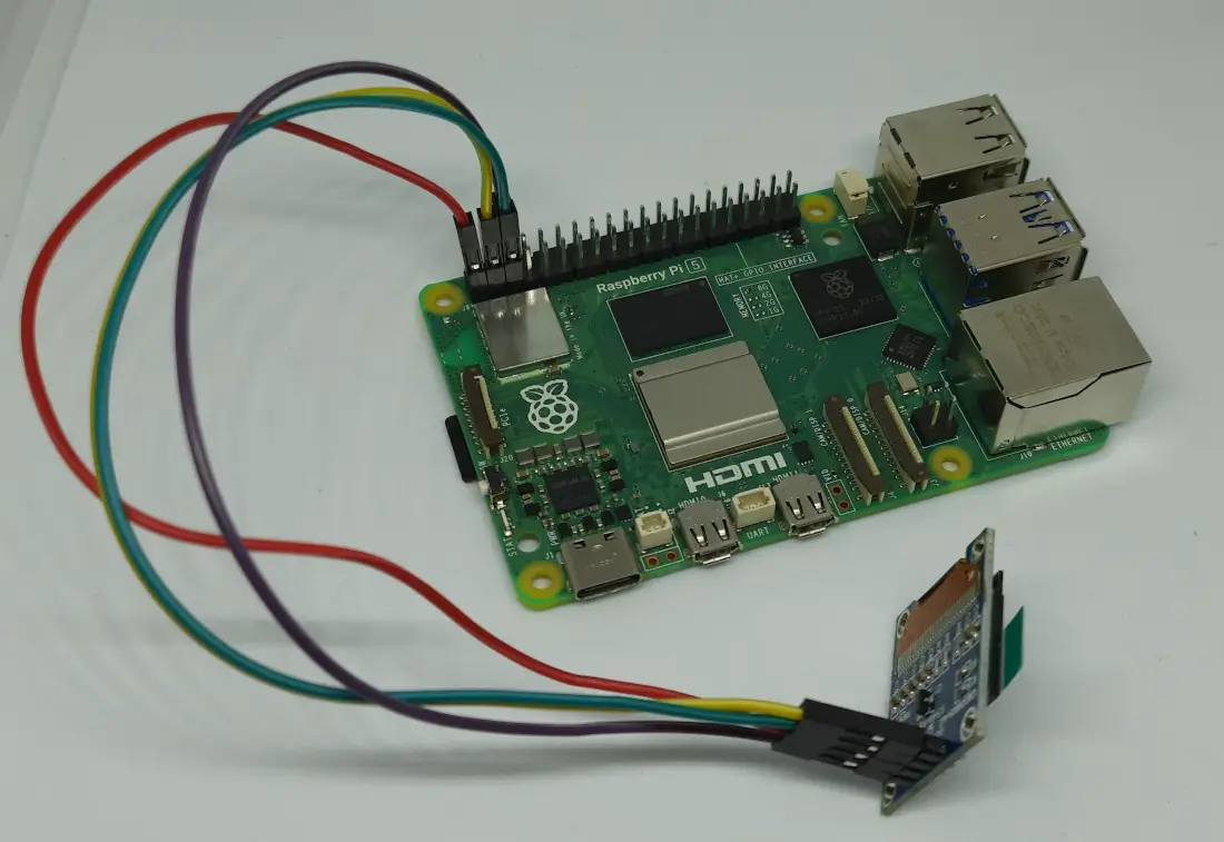
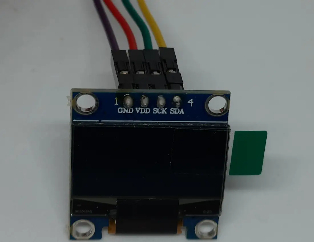
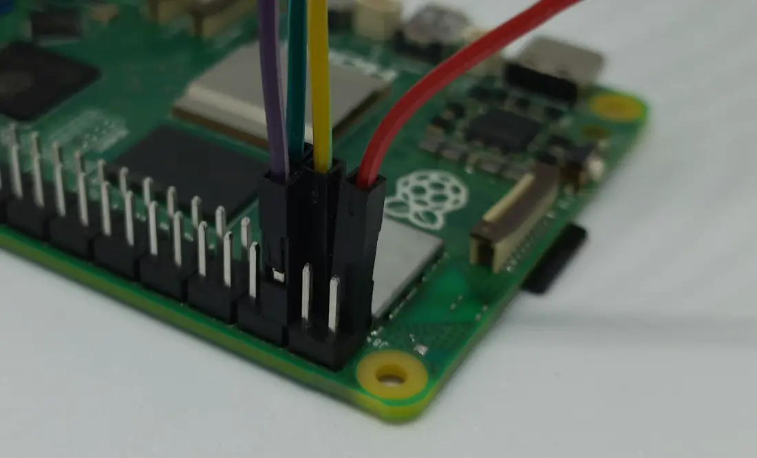
Some pictures from my lab follow:
Prepare the Operating System
Prepare the Operating System
Please start installing your favourite Operating System for Raspberry PI. You can use the Raspberry PI OS Lite, as it provides a headless, faster environment for low-capabilities Raspberry PI computer boards. But you can also use Raspberry PI OS Desktop, in this case working from its internal terminal. You can check the difference between the two OS from my Raspberry PI OS Lite vs Desktop: comparison between the 2 distributions.
For this tutorial, I’m going to use the Raspberry PI OS Lite 64-bit.
Make your OS up-to-date. From the terminal, please use the following command:
sudo apt update -y && sudo apt upgrade -yWe also need pip (the Python package manager) and the I2C tools. From terminal:
sudo apt install python3-pip i2c-tools -yEnable I2C
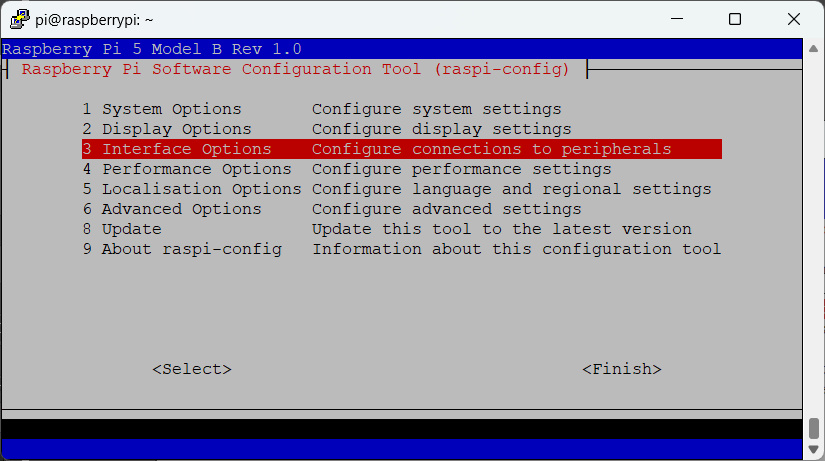
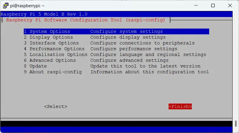
The SSD1306 OLED display works with an I2C connection. So, we need to enable it in our Raspberry PI, by using the built-in “raspi-config” tool:
sudo raspi-configPlease select “Interface Options”:
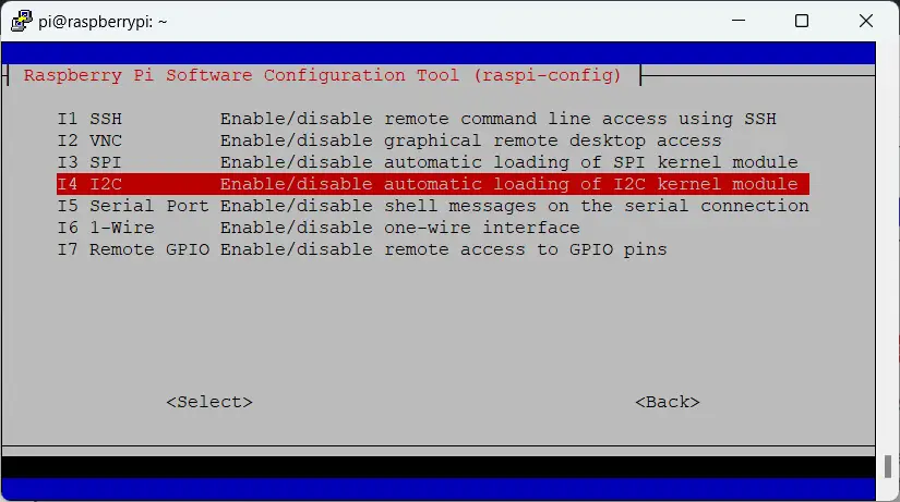
Then select “I2C”:
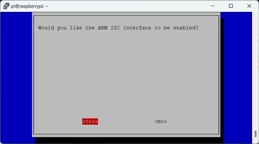
In the following screen, please select yes:
The following screen will confirm that the I2C interface has been enabled:
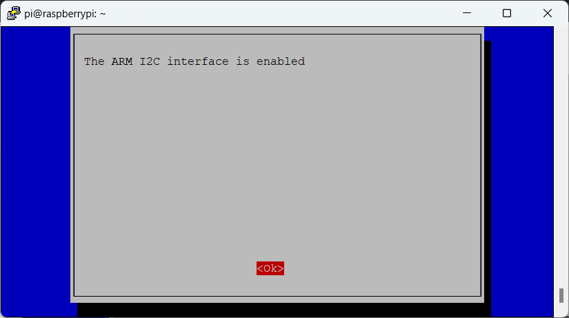
Back to home, select finish:
It’s recommended to reboot your Raspberry PI after enabling the I2C
sudo rebootIf you already connected the wiring, you should be able to detect the I2C device as follows with a line identifying a new “i2c /dev entries driver”:
pi@raspberrypi:~ $ dmesg | grep i2c
[    2.840754] brcmstb-i2c 107d508200.i2c:  @97500hz registered in interrupt mode
[    2.867604] brcmstb-i2c 107d508280.i2c:  @97500hz registered in interrupt mode
[    4.266195] i2c_dev: i2c /dev entries driver
We can detect the SSD1306 address on I2C bus with the “i2cdetect” tool:
pi@raspberrypi:~ $ i2cdetect -y 1
     0  1  2  3  4  5  6  7  8  9  a  b  c  d  e  f
00:                         -- -- -- -- -- -- -- --
10: -- -- -- -- -- -- -- -- -- -- -- -- -- -- -- --
20: -- -- -- -- -- -- -- -- -- -- -- -- -- -- -- --
30: -- -- -- -- -- -- -- -- -- -- -- -- 3c -- -- --
40: -- -- -- -- -- -- -- -- -- -- -- -- -- -- -- --
50: -- -- -- -- -- -- -- -- -- -- -- -- -- -- -- --
60: -- -- -- -- -- -- -- -- -- -- -- -- -- -- -- --
70: -- -- -- -- -- -- -- --
The “3c” means that you correctly identified the SSD1306 OLED display. If you get a different address, you may have a different hardware.
Install luma.oled Library
Python doesn’t have a built-in library to manage our SSD1306 OLED display, so we need to install the useful “luma.oled” library in our Raspberry PI. For this task, we need to create a Python Virtual Environment in Raspberry PI (see the referenced article in order to understand how to manage virtual environments):
python3 -m venv my_project --system-site-packages
source my_project/bin/activate
Please note that we’ll need to activate the virtual environment to use the OLED after every use of our scripts after a Raspberry PI reboot or logout.
Now we can use pip to install the required library:
pip3 install luma.oledLuma.oled requires that your user has access to hardware interfaces. We can grant this access with the following command:
sudo usermod -a -G spi,gpio,i2c $USERTest SSD1306 with Raspberry PI
Now we’re ready to perform our tests.
Please download in your Raspberry PI my script with our first test:
wget https://peppe8o.com/download/python/oled/ssd1306-test-01.pyThis is a very simple test, which prints a message in your OLED display. But it is useful to introduce some common concepts. The following will describe this script line by line.
At the beginning, we import the required libraries. Please note that we also import the sleep function, which keeps the display active to give you enough time to see the results (I’ll explain this later):
from luma.core.interface.serial import i2c
from luma.core.render import canvas
from luma.oled.device import ssd1306, ssd1325, ssd1331, sh1106
from time import sleep
Then we initialize the SSD1306 OLED display. If you have a different display model (from the models supported by luma) you can change the “ssd1306()” with your display model. Also, the “rotate” input enables you to rotate the screen with allowed values in 0, 1, 2, and 3.
serial = i2c(port=1, address=0x3C)
device = ssd1306(serial, rotate=0)
Then we draw 2 text lines. The first text line (“Hello World”) will print at the cartesian point with x=10 and y=40. This text will be displayed in white (we have monochromatic display, so white means that pixels are powered on). Similarly, we’ll print the second line (“from peppe8o.com!”) at the point with X=10 and Y=50.
Please note that the display printing effectively appears at the end of the “with canvas(device)….” block. So, the library takes all the commands inside this block and prints them all together:
with canvas(device) as draw:
    draw.text((10, 40), "Hello World", fill="white")
    draw.text((10, 50), "from peppe8o.com!", fill="white")
The final “sleep” line makes the display output persistent for 5 seconds:
sleep(5)With the OLED display, you will keep the printed output active until the Python script ends or until you run another “with canvas(device)….” block. A new block will also clear all the existing objects before printing new ones. You can also force a display to erase with the “device.clear()” command .
You can run this script with the following command:
python3 ssd1306-test.pyYou will get the following output:
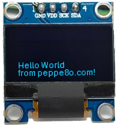
An additional tip, you can also write multiple lines with the “\n” escape character. So, printing “Hello World” and “from peppe8o.com!” in two different lines will be quite the same as printing “Hello World\nfrom peppe8o.com!” in a single line. I used “quite” as in two draw.text statements you can control the spacing between the two lines, while using the escape will use the library default spacing.
Now that we have covered the basics of the luma.oled library usage, I will show you some additional primitive forms to use. They will require the same “import” section and the same serial/device variables initialization.
Primitive Forms
Besides a simple text, you can also draw several primitive forms. This chapter will show you these forms with their related commands and options. You can get a python script showing all these forms together with the following:
https://peppe8o.com/download/python/oled/ssd1306-test-02.pyYou can run it with the Python command:
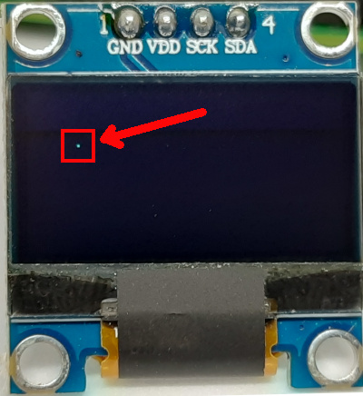
python3 ssd1306-test-02.pyDraw a point (or a list of points)
You can draw a single point by providing the point coordinates within a list object similar to [ (x, y) ], as follows:
with canvas(device) as draw:
    draw.point([(20, 20)], fill="white")
You can also draw multiple points by adding their coordinates in the same list object, similar to
[ (x_1, y_1), (x_2, y_2), (x_3, y_3), (x_4, y_4), … ]
as follows:
with canvas(device) as draw:
    draw.point([(20, 20), (70, 60)], fill="white")
The result will be as in the following picture:
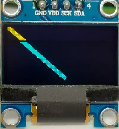
Draw a line
You can draw a line by defining the two points at the start and the end of the line in coordinates similar to what was seen in the previous example. With the line, you can also define the line width, making it more or less thick:
with canvas(device) as draw:
    draw.line([(0,0), (70,60)], fill="white", width = 5)
And the result follows:
Draw a rectangle
As for the line, a rectangle is defined by two points (at the top-left corner and bottom-right corner) in coordinates. With the rectangle, a new variable named “fill” will allow us to control the colour inside the form:
with canvas(device) as draw:
    draw.rectangle([(20, 0), (70, 60)], outline="white", fill="black")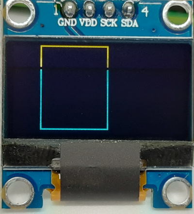
A common need is to create a frame around the whole display. In this case, we can use the “device.bounding_box” variable instead of providing coordinates of the display start and end:
with canvas(device) as draw:
    draw.rectangle(device.bounding_box, outline="white", fill="black")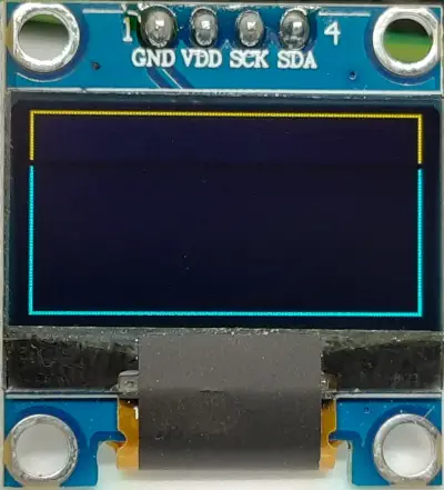
The last rectangle option allows you to create rounded corners for your form by setting the radius variable:
with canvas(device) as draw:
    draw.rounded_rectangle([(20, 0), (70, 60)], radius=10, fill=None, outline="white", width=1, corners=None)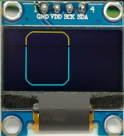
Draw an Ellipse
The ellipse can be imagined as the form closed into a rectangle. So, you can draw it by identifying the rectangle coordinates and giving it the fill and outline colours, as well as the border width:
with canvas(device) as draw:
    draw.ellipse([(0, 0), (70, 60)], fill="white", outline="black", width=1)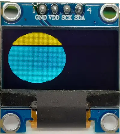
Draw an Arc
Similarly, you can imagine the arc as part of the same ellipse. The difference is that you will explicit the starting angle and the ending angle, where 0 means the middle-right side of the ellipse. The following example shows an arc from 0 degrees to 90 degrees. Other options are the same as seen in the previous examples:
with canvas(device) as draw:
    draw.arc([(0, 0), (70, 60)], 0, 90, fill="white", width = 1)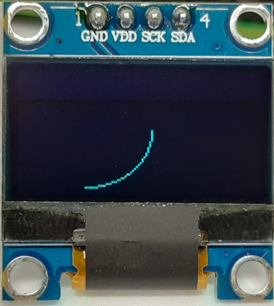
Draw a Chord
With a chord, you will automatically get also a line connecting the start point and the end point of the corresponding arc:
with canvas(device) as draw:
    draw.chord([(0, 0), (70, 60)], 0, 90, outline="white", fill="black", width = 1)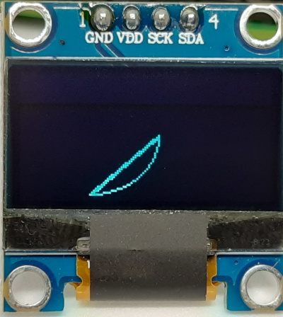
Draw a Pie Slice
The pie slice is still similar to the arc form. Differently from the chord, both the starting point and the end point are connected to the centre of the outbound form:
with canvas(device) as draw:
    draw.pieslice([(20, 0), (70, 60)], 0, 90, fill="white", outline=None, width=1)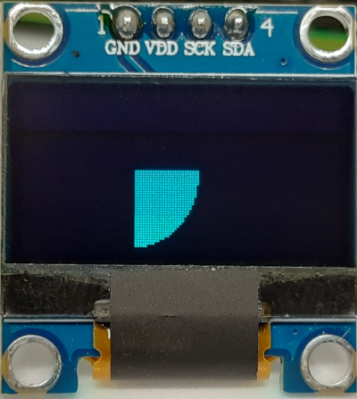
Draw a Polygon
The last primitive form is a polygon. It is a series of lines, where the last line end is automatically connected to the start point of the first line:
with canvas(device) as draw:
    draw.polygon([(20, 0), (70, 10), (60, 60), (15, 63)], fill=None, outline="white", width=1)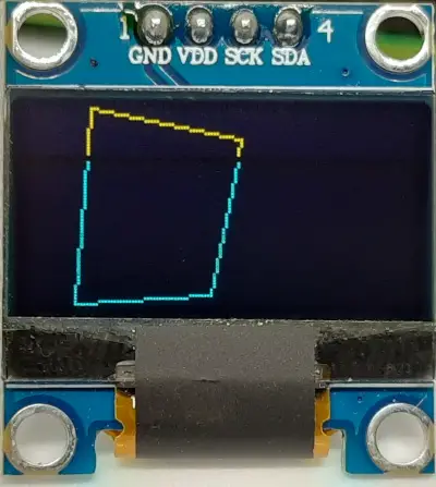
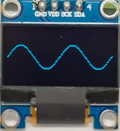
Draw a Function
Another funny example to test is to draw a function like into a Cartesian chart. I’ve arranged a script in this way, drawing a sinusoidal curve.
The Python script is available from my download area:
wget https://peppe8o.com/download/python/oled/ssd1306-test-03.pyAnd the result is the following one, where points will appear one by one from left to right:
Running Luma Examples
The Luma GitHub page also includes a number of cool examples to run, allowing you to learn how to create even funny animations. Not all the provided examples will work with our SSD1306 OLED display, but there are a lot to try.
Before using them we need to install git:
sudo apt install git -yLuma examples will also require some additional packages to install:
sudo apt install python3-dev python3-pip python3-numpy libfreetype6-dev libjpeg-dev build-essential libsdl2-dev libsdl2-image-dev libsdl2-mixer-dev libsdl2-ttf-dev libportmidi-dev -yAt this point, we can get a complete duplicate of the luma examples folder from GitHub with the “git clone” command:
git clone https://github.com/rm-hull/luma.examples.gitNow, you will find the examples to run by entering the related folder from your Raspberry PI storage:
cd luma.examples/examples/What’s Next
Want to know more about cool projects to do with Raspberry PI computer boards? In this case, the right resource for you is my Raspberry PI tutorial pages.
Enjoy!

Open source and Raspberry PI lover, writes tutorials for beginners since 2019. He's an ICT expert, with a strong experience in supporting medium to big companies and public administrations to manage their ICT infrastructures. He's supporting the Italian public administration in digital transformation projects.
![]()
![]()
![]()
![]()
![]()
![]()
![]()