Some links in this post may be affiliate links. We may get paid if you buy something or take an action after clicking one of these, but without addictional costs for you compared to direct buying.
Last Updated on 9th June 2024 by peppe8o

Tilt ball switch are small and cheap electronic sensors able to detect inclination. While not being as accurate like accelerometers, they are small, inexpensive and easy to use. For this reason tilt ball switches are popular for toys and gadgets.
Tilt ball switch are usually made of an internal cavity with a free conductive mass inside. When this switch is in vertical position, conductive mass goes down and connects terminals. When it is in horizontal position, conductive mass moves from terminals, so resulting in current not passing:

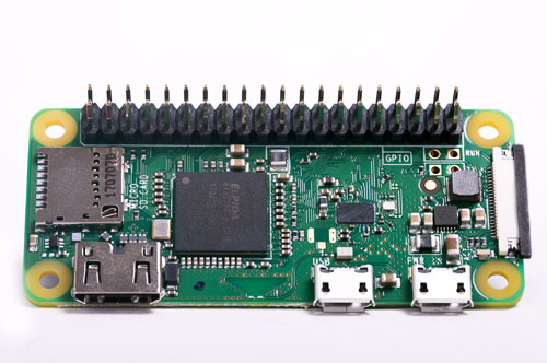
In this tutorial I’ll show you how to use a simple Tilt Ball Switch with your Raspberry PI with a LED detecting sensor position. I’ll use a Raspberry PI Zero W, but this guide applies also to newer Raspberry PI boards. Small resistors (330 Ohm) will be also used to protect from power outage that can damage your Raspberry PI board.
What We Need

As usual, I suggest adding from now to your favourite e-commerce shopping cart all the needed hardware, so that at the end you will be able to evaluate overall costs and decide if to continue with the project or remove them from the shopping cart. So, hardware will be only:
- Raspberry PI Zero W (including proper power supply or using a smartphone micro usb charger with at least 3A) or newer Raspberry PI Board
- high speed micro SD card (at least 16 GB, at least class 10)
- Solderless breadboard
- Dupont Wiring
- Tilt ball Switch
- Resistors
Step-by-Step Procedure
Simple Wiring Configuration
The simplest wiring configuration, without Python programming, implements a circuit where Raspberry PI only powers a LED which lights ON when tilt ball switch is in vertical position. LED will light OFF when tilt ball switch is in horizontal position. This wiring configuration is shown in following picture. Consider that longer PIN need to be connected to positive side.

You can both wire directly components or use a breadboard to make connections stable. After wiring is complete, simply power on Raspberry PI. As said, no python programming is needed.
Following picture shows what happens when tilt ball sensors is in vertical position:

Following picture shows what happens when tilt ball sensors is in horizontal position:

Inverse Configuration with Python
Following configuration powers on LED when tilt ball sensor is in horizontal position, while leaving LED off when tilt ball switch is in vertical position. This can be achieved both with electronic components (including some addictional resistors and a transistor) or controlling sensor status with Python. I’ll follow second option, also to show how to manage tilt sensor from Python.
Inverse Configuration Wiring Diagram
Following picture shows wiring diagram. Please note that LED longer PIN is connected to protection resistor and the to a configurable PIN. Tilt Sensor has also a protection resistor to avoid a direct circuit closure between 3.3V PIN and our reading PIN:

Prepare Operating System
Start preparing your OS by installing Raspberry PI OS lite or Raspberry PI OS Desktop. In first case, you’ll configure your RPI from a remote terminal connection. In second case, you can configure it from a local terminal session.
Make your OS updated:
sudo apt update -y && sudo apt upgrade -y Python is already installed on Raspberry PI OS. RPI.GPIO should be already installed (otherwise, you can get it installed with the command “sudo apt install python3-rpi.gpio”).
Prepare Python Program to Manage Tilt Sensor and LED
You can get my python pragram to Raspberry PI with following terminal command:
wget https://peppe8o.com/download/python/tiltballswitch.pyThis simple program is explained in following row by row.
First of all, required libraries are imported:
import sys
import RPi.GPIO as GPIO
Then used PINs are associated to variables, in order to make code easier to read. ReadPIN is connected to tilt ball sensor and will be the PIN where we’ll read if tilt is ON ord OFF. triggerPIN is connected to positive LED side. According to last wiring diagram:
readPIN = 19
triggerPIN = 26
Set GPIO pins to Broadcom naming convention (BCM) and set readPIN as input and triggerPIN as output. readPIN will be also configured with pull_up_down setting to down. This gets a stable signal when reading pin is not connected, avoiding an undefined state that can be read from Raspberry PI as unstable state:
GPIO.setmode(GPIO.BCM)
GPIO.setup(triggerPIN,GPIO.OUT)
GPIO.setup(readPIN,GPIO.IN, pull_up_down=GPIO.PUD_DOWN)
The core part of this code is really simple. With next loop, RPI continuously checks readPIN value, which will be 0 (or LOW) when the tilt sensor is in horizontal position and 1 (or HIGH) when tilt switch is in vertical position. triggerPIN is set to inverse value with “not” function, so readPIN=0 means triggerPIN=1 and readPIN=1 means triggerPIN=0. LED will be powered on when triggerPIN is set to 1:
try:
  while True:
    GPIO.output(triggerPIN,not(GPIO.input(readPIN)))
Last part will manage script exit (you can exit from script execution with interrupt signal from CTRL+C keyboard pression) and clean GPIO status before exiting:
except KeyboardInterrupt:
  print('interrupted!')
  GPIO.cleanup()
Running Python Script
Run this script from terminal:
python3 tiltballswitch.pyTilt sensor vertical position will leave LED off:

Tilt sensor in the horizontal position will power on our LED:

As said, to stop Python script simply press CTRL+C.
Enjoy!

Open source and Raspberry PI lover, writes tutorials for beginners since 2019. He's an ICT expert, with a strong experience in supporting medium to big companies and public administrations to manage their ICT infrastructures. He's supporting the Italian public administration in digital transformation projects.

