
In this tutorial, we will make stepper motor movement in clock and counterclockwise with Arduino Uno. The stepper motor is widely used in the application of the movements such as vehicles, and CNC printers.
Introduction
An Arduino Uno or other comparable microcontrollers may control stepper motors using the popular and frequently used A4988 stepper motor driver module. It offers a quick and effective method for connecting stepper motors to the Arduino, allowing for precise control of their motion. Bipolar stepper motors, which are frequently used in numerous applications including 3D printers, CNC machines, robotics, and automation systems, can be driven by the A4988 driver module. It can manage motors with a voltage range of 8V to 35V and a maximum current rating of up to 2A per coil.
Working principle of A4988 and stepper motor
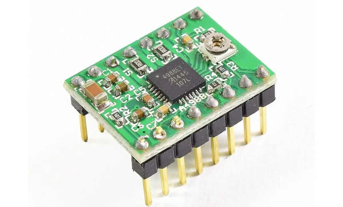
The A4988 stepper motor driver has sixteen pins. Using an Arduino or other comparable microcontroller, it can control bipolar stepper motors by using the wiring to the 1A, 2A, 1B, and 2B.
It operates by communicating step and direction commands to the driver module, which directs the motion of the motor. The driver features configurable current limitations to safeguard the motor and itself, and it supports micro-stepping for more fluid action.
It also has an enabling pin that can be used to turn on or off the motor coils.
What We Need

As usual, I suggest adding from now to your favourite e-commerce shopping cart all the needed hardware, so that at the end you will be able to evaluate overall costs and decide if to continue with the project or remove them from the shopping cart. So, hardware will be only:
Step-by-Step Procedure
Wiring Diagram of Stepper motor with driver and Arduino
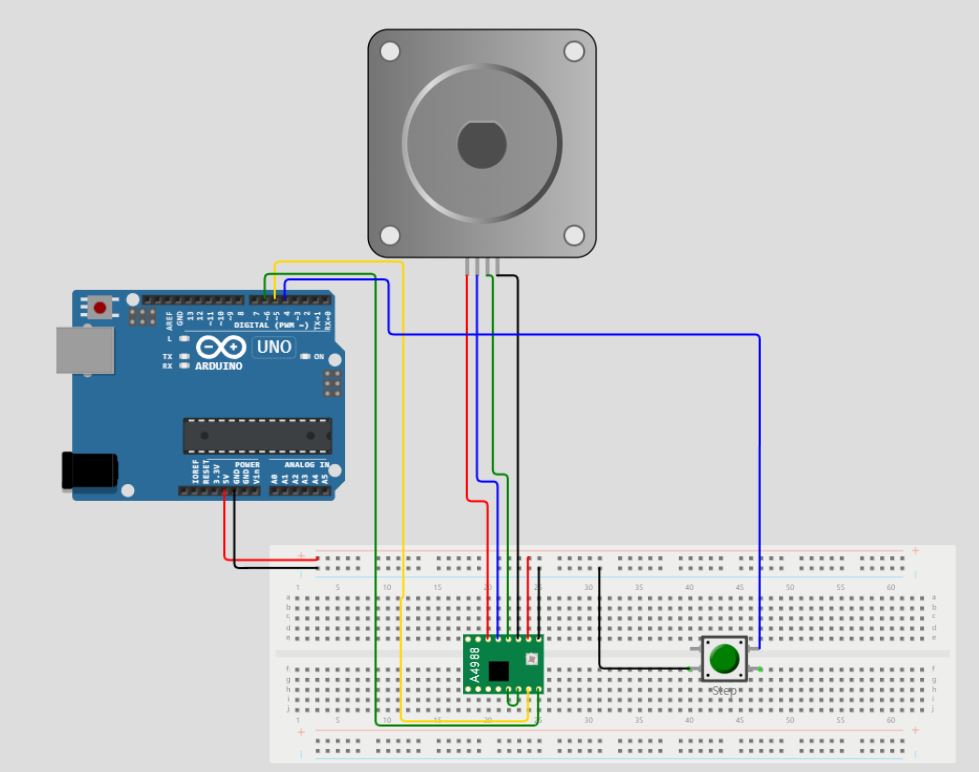
The picture represents the wiring diagram of the stepper motor, stepper motor driver, and a button with Arduino Uno. The stepper motor driver requires continuous high and low values so it’s better to connect with the PWM pin (Can also use the digital pins as well). The PWM in your Arduino can be identified with a sign “~”. Here connects to pins 5 and 6. The wiring diagram with the Arduino connects in this pattern.
Note: The button is connected to pin 4 for high and low purposes. The green small wire at A4988 needs to be short between pins 5 and 6.
| Arduino | A4988 Driver | Stepper motor |
| 5 | Pin 7 (lower left side) (Yellow wire) | |
| 6 | Pin 8 (green) | |
| VCC | Pin 15 (red) | |
| Pin 16 (black) | GND | |
| Pin 11 (top left side) (red wire) | Pin 1 (left side) | |
| Pin 12 (purple wire) | Pin 2 | |
| Pin 13 (green) | Pin 3 | |
| Pin 14 (black) | Pin 4 | |
| Pin 6 | 2 |
Get the code and remote control Libraries
Connect your PC to Arduino and open Arduino IDE. For the very first steps, you can refer to Connecting Windows PC with Arduino tutorial. You can get the .ino code from my download area with the following link:
Code Explanation
Section 1: Variables Before Setup section
In this section, the code defines the pins (“STEP_PIN” and “DIR_PIN”), and the button (“button”) that it uses to drive the stepper motor.
#define STEP_PIN 5
#define DIR_PIN 6
#define button 4
The stepper motor’s STEPS_PER_REV variable describes how many steps are required to complete one complete revolution.
const int STEPS_PER_REV = 200;The amount of micro stepping employed for smooth motion is determined by MICROSTEP_RESOLUTION. The stepper motor and button input are controlled by the program using these definitions.
const int MICROSTEP_RESOLUTION = 16;Section 2: Setup section
In the setup() function, the STEP_PIN and DIR_PIN are set up as output pins, and the button pin is set up as an input pin. This makes it possible to read the button’s program state and control the stepper motor.
void setup() {
  // Set the step and direction pins as outputs
  pinMode(STEP_PIN, OUTPUT);
  pinMode(DIR_PIN, OUTPUT);
  pinMode(button, INPUT_PULLUP);
}
Section 3: Loop section
In the loop section, using digitalRead(), the code determines whether the button presses (LOW state). If so, it runs the rotateClockwise() function to rotate the stepper motor one revolution clockwise.
void loop() {
  if (!digitalRead(button))
  {
rotateClockwise(1);
  }
If not, it uses the rotateantiClockwise() function to turn the motor counterclockwise by one revolution.
else {rotateantiClockwise(1);}
The software uses delay(1000) to pause for 1 second after the motor movement before resuming the loop.
  delay(1000);
}
Section 4: Functions for clockwise and counterclockwise movement
There are two functions for clockwise and counterclockwise movement. Both functions require as argument the number of revolutions required for the stepper motor.
For the rotateClockwise() function, the direction pin is set to rotate in the clockwise direction at HIGH state of the button PIN:
void rotateClockwise(int revolutions) {
  digitalWrite(DIR_PIN, HIGH);
The total number of steps to perform comes from a simple calculation using the number of revolutions, the number of steps for each revolution, and the set resolution:
int steps = revolutions * STEPS_PER_REV * MICROSTEP_RESOLUTION;The motor then steps by switching the STEP_PIN to HIGH and LOW values repeatedly. The delay functions can be used to set the speed of rotation (lower means faster), keeping in account the capabilities of your stepper motor. For this value, performing multiple tests will give you a reliable value:
  for (int i = 0; i < steps; i++) {
    digitalWrite(STEP_PIN, HIGH);
    delayMicroseconds(500);
    digitalWrite(STEP_PIN, LOW);
    delayMicroseconds(500);
  }
}
Similar to rotateClockwise(), rotateAntiClockwise() causes the direction pin to rotate in the opposite direction (LOW state). The speed of the motor movement controls by a delay in both processes. For the required speed, the delay time varies.
void rotateantiClockwise(int revolutions) {
  digitalWrite(DIR_PIN, LOW);
  int steps = revolutions * STEPS_PER_REV * MICROSTEP_RESOLUTION;
  for (int i = 0; i < steps; i++) {
    digitalWrite(STEP_PIN, HIGH);
    delayMicroseconds(500);
    digitalWrite(STEP_PIN, LOW);
    delayMicroseconds(500);
  }
}
Results
Initially, when no button presses the stepper motor moves in a counterclockwise direction as can be seen from the folowing gif:
When the button is pressed it moves in the clockwise direction as given in the following picture:
What’s Next
Please find more tutorials on Arduino in peppe8o Arduino archives.
Enjoy!
Umar Jamil
For any queries and help for work, please contact me at:
Whatsapp: +92-346-661-7017/ Link
Fiverr: Link

I'm an Electronic Engineer, well-skilled to solve the issues of hardware and software. I do have laboratory which contains unlimited sensors and modules for testing the working. Also, I am experienced in Arduino programming, Android mobile application, microcontroller programming, IOTs and embedded projects. I provide services to control, realize the sensor data in the Mobile Application. For any queries and help for work Contact: Whatsapp:+92-346-661-7017 Email: umarjamil0007@gmail.com
![]()


