
Last Updated on 27th June 2025 by peppe8o
In this article, I’ll show you how to use a Photoresistor with Raspberry PI computer boards and Python to detect if a light level is high or low.
About Photoresistors
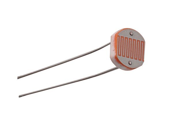
A photoresistor (also known as photocell or light sensor) is a Light Dependent Resistor (LDR). As the name suggests, these components act just like a resistor, changing their resistance in response to how much light is falling on it.
Usually, photoresistors have a very high resistance (around 50k ohm) in near darkness and very low resistance (around 500 ohm) in bright light.
This component is used to manage electronic or electric devices to respond to light conditions, enabling or disabling functions.
Photoresistors are analogic components. So it can be used with microcontrollers having analogic inputs (like the Raspberry Pi Pico or Arduino) to read the real light level. Unfortunately, Raspberry PI computer boards have only digital inputs (with the threshold between High and Low being around 1.3V). This means that, without specific analogic-to-digital hardware, we wouldn’t be able to read anything then high or low values.
Help in this sense comes from a simple circuit integrating a capacitor in series with the photoresistor (as shown in the following picture):
- When the R1 photoresistor gets light on it, it reduces its internal resistance and the related voltage drop across it. The reading point will result near the value of VCC. This will make the C1 capacitor quickly load to a value near the VCC
- When the R1 photoresistor is in dark conditions, it increases its internal resistance and the related voltage drop across it. The reading point will be near the value of GND. This will make the C1 capacitor slowly load to a higher value than GND
By using the described principle, from a Raspberry PI you can continuously discharge the C1 capacitor and see how much time it takes to get a High value (above 1.3 V, which triggers the high value on Raspberry PI readings). The faster it triggers the high value, the higher the light hitting the photoresistor.

In our case, with the GPIOZero library, we don’t need to care about all the process as the library does the job for us.
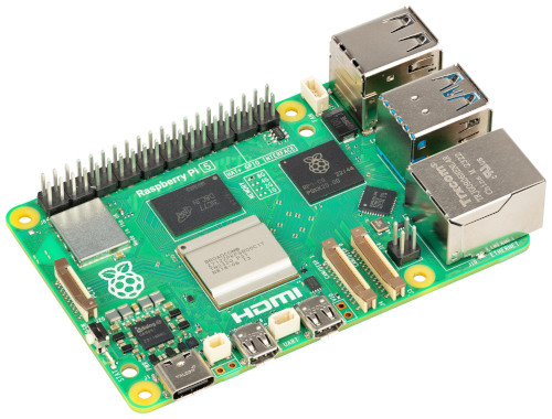
For this tutorial, I’ll use a Raspberry Pi 4 Model B, but this article also applies to any Raspberry PI computer board.
What We Need
As usual, I suggest adding from now to your favourite e-commerce shopping cart all the needed hardware, so that at the end you will be able to evaluate overall costs and decide if to continue with the project or remove them from the shopping cart. So, hardware will be only:
- Raspberry PI Computer Board (including proper power supply or using a smartphone micro USB charger with at least 3A)
- high-speed micro SD card (at least 16 GB, at least class 10)
- Dupont wirings
- a Photoresistor
- a Capacitor (I used a 10uF capacitor)
- (optional) a Breadboard
Wiring Diagram
Please arrange the wiring diagram as shown in the following picture, according to the Raspberry PI pinout. Please note that VCC+ is connected to a 3.3V port, to leave an acceptable voltage entering in reading GPIO (GPIOs can read up to 3.3V, otherwise you risk damaging it):

The following picture also shows you my project assembly:


Step-by-step Procedure
Install Raspberry PI OS Operating System
The first step is installing the Raspberry PI OS Lite to get a fast and light operating system (headless). In this case, you will need to work from a remote SSH terminal. If you need a desktop environment, you can also use the Raspberry PI OS Desktop, in this case working from its terminal app. Please find the differences between the 2 OS versions in my Raspberry PI OS Lite vs Desktop article.
Make sure that your system is up to date. Connect via SSH terminal and type the following command:
sudo apt update -y && sudo apt full-upgrade -yWe also need to use the pin_factory to get readings different from a stuck “0.0”. To make it work, we must enable and start the gpiod service on our Raspberry PI computer board. This task can be performed with the following terminal commands:
sudo systemctl enable pigpiod.service
sudo systemctl start pigpiod.service
The GPIOZero library is already installed and it gives you the LightSensor() class to manage the photoresistor from the Raspberry PI. I’ll show you a basic and an advanced usage of this class.
Get the Python Script for Photoresistor with Raspberry PI – Base Example
This example will show you how to get the light values read from the Raspberry PI. Please note that the read values are in the range from 0 to 1, and they don’t represent an absolute measurement of the light. So, with this script you will be able to tune the readings get from light.
Please download it from my download page with the terminal command:
wget https://peppe8o.com/download/python/photoresistor/photoresistor_rpi_basic.pyThe following will explain the script line by line.
In the beginning, we import the required libraries. We need the LightSensor class from the gpiozero library, the sleep class (to add a pause between two different readings), and the PiGPIOFactory to set the PIN factory to use:
from gpiozero import LightSensor
from time import sleep
from gpiozero.pins.pigpio import PiGPIOFactory
them, we can initialise the LightSensor class. It is important here to note the charge_time_limit value. By default, it is set to 0.01, and it is strictly related to the used capacitor. If you use one with a different capacity from mine (which is 10uF) you can try setting this variable to different values to tune your results.
Please also set the PIN value is your reading point is wired with a different Raspberry PI’s PIN compared with my schema.
sensor = LightSensor(pin = 14, charge_time_limit = 0.1, pin_factory = PiGPIOFactory())The main loop will simply read the sensor values and print them every half second:
while True:
    print(sensor.value)
    sleep(0.5)
Run the Base Example
You can run the script by typing the following command:
python photoresistor_rpi.pyAnd you will get results similar to the following. You can give your sensor more or less light to check that it works.
pi@raspberrypi:~ $ python photoresistor_rpi_basic.py
0.8088500000000001
0.80867
0.8091200000000001
0.8084800000000001
0.42534000000000005
0.30783000000000005
0.13038000000000005
0.10945000000000005
0.10896000000000006
0.02426000000000006
0.0
0.0
You can use CTRL+C interrupt signal to stop the Python script.
Get the Python Script for Photoresistor with Raspberry PI – Advanced Example
In this example, I’ll show you how to create a custom function to run when your photoresistor moves from light to dark and vice versa, as well as what LightSensor property gives us this feedback about the current state. Moreover, we’ll see how to set a threshold to define the readings as “light” or “dark”.
Please download the new example script from my download page with the terminal command:
wget https://peppe8o.com/download/python/photoresistor/photoresistor_rpi_advanced.pyThe following will explain the script line by line.
We need again the same classes:
from gpiozero import LightSensor
from gpiozero.pins.pigpio import PiGPIOFactory
from time import sleep
The first difference comes at the LightSensor initialisation. The threshold variable (default to 0.1) allows us to set what it the reading value which we’ll define as the edge between light and dark conditions. Here, I’m going to set it to a higher value (0.5):
sensor = LightSensor(pin = 14, charge_time_limit = 0.1, threshold = 0.5, pin_factory = PiGPIOFactory())At this point, the script defines 2 custom functions: the callback_light and the callback_dark. The first one will be executed when the environment moves from dark to light, while the second one will manage the opposite conditions. For this example the just print a string on the terminal, but you can add your code to run there.
def callback_light():
  print("There's light here!")

def callback_dark():
  print("It's going to be dark!")
We can now assign our callback functions to the related methods of the LightSensor to make them work properly. You don’t need to call them in your main loop: with the following setting, they will automatically call the right function by interrupting the code execution and then resuming it after they have processed their lines.
sensor.when_light = callback_light
sensor.when_dark = callback_dark
The main loop adds another property: the light_detected. This will always be 1 (True) while the light lever is higher than the threshold, while it will be o (False) with the read value lower than it:
while True:
  if sensor.light_detected: print("Light detected trigger on!")
  sleep(0.5)
Run the Advanced Example
You can use this script with the following command:
python photoresistor_rpi_advanced.pyYou will get something similar to the following:
pi@raspberrypi:~ $ python photoresistor_rpi_advanced.py
Light detected trigger on!
Light detected trigger on!
Light detected trigger on!
Light detected trigger on!
Light detected trigger on!
Light detected trigger on!
It's going to be dark!
There's light here!
Light detected trigger on!
Light detected trigger on!
Light detected trigger on!
Light detected trigger on!
Light detected trigger on!
Light detected trigger on!
Light detected trigger on!
Light detected trigger on!
Light detected trigger on!
Light detected trigger on!
It's going to be dark!
There's light here!
Light detected trigger on!
As you can note, the callback functions will run only at the edges of the trigger, even if outside the main loop. On the other hand, the light_detected keeps pushing True values during the light conditions and returns False in dark conditions.
Enjoy!

Open source and Raspberry PI lover, writes tutorials for beginners since 2019. He's an ICT expert, with a strong experience in supporting medium to big companies and public administrations to manage their ICT infrastructures. He's supporting the Italian public administration in digital transformation projects.
![]()
![]()
![]()
![]()
![]()
![]()
![]()


Unfortunately I always get state 1, even though a LED after transistors shows there is a current when it is dark. But it’s impossible to get voltage small enough on pin 14 with these resistors…
Now I see. The Led was the reason. Everything works now.
Any hints for a python noob… Would like to adapt your script to write output to a log file. Log file entries would only be written when the state changes (from 0 > 1, and from 1 > 0). Plus… entries have to be timestamped. (Am monitoring a thermostat’s LED indicator.) So, log file would look something like:
2022-04-25 20:36:07 1
2022-04-25 20:41:39 0
2022-04-25 20:57:19 1
…
Hi Jon
you must combine my python code with the following:
from datetime import datetimef = open(r"path_to_file.txt","a")# opens the file (a=append, w=write, r=read)now = datetime.now()# current date and timedate_time = now.strftime("%Y-%m-%d %H:%M:%S")#this formats the datetimef.write(date_time+str(GPIO.input(readPIN))+"\n")# the final \n adds a carriage returnf.close()# close the fileThe first import goes at the beginning of code.
The f.open() goes just after importing the libraries.
The third part goes in the “while True:” loop.
The f.close() goes in the “except KeyboardInterrupt:” part.
Please let me know if this works.
Giuseppe
You better to select resistor 100K based on photo resistor resistance. I added a potentiometer to adjust the sensitivity. I used a 30K resistor instead of 100K in series with a 100K potentiometer. Now it works well. For raspberry pi zero, logic level low is less than 1.4V.
Thanks for your information.
Sorry for the late reply and thank you very much for your feedback, Mohammad!
Thanks for the tip on pin_factory. My red/green led and photoresistor test was dead at 0.0 until that fix
thank you for your feedback!