Last Updated on 15th March 2025 by peppe8o
In this tutorial, I will show you how to connect and use an Incremental Rotary Encoder with Raspberry PI computer boards. I will also show you the Python code, explaining it line by line.
If you need to use Rotary Encoders with Raspberry PI Pico, please refer to my Rotatory Encoder with Raspberry PI Pico tutorial.
About Incremental Rotary Encoders
I will not be long in the device description as I already wrote the working principle in the previously linked post about Raspberry PI Pico.
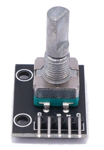
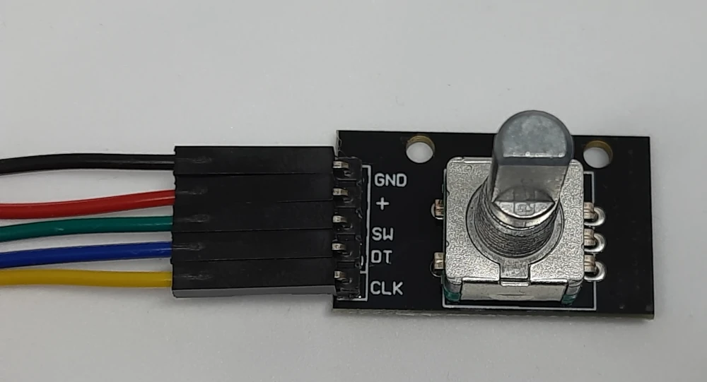
Nevertheless, here I will rewrite the encoder pinout for convenience. The Incremental Rotary Encoder pinout includes 5 PINs:
| PIN Label | Description |
|---|---|
| GND | Connected to the ground |
| + (or VCC) | Connected to the power supply |
| SW | Connected to the shaft button, active at low values |
| DT | Digital PIN detecting the rotation direction |
| CLK | Digital PIN detecting the rotation movement |
Some rotary encoder models may miss the SW PIN (as, with them, you can’t push the shaft). You should be able to customize the following code according to your needs.
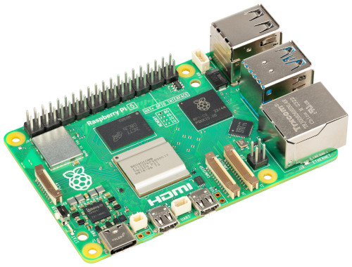
For this guide, I’ve used a Raspberry PI 4 model B computer board, but the following procedure should work with any Raspberry PI computer board.
What We Need
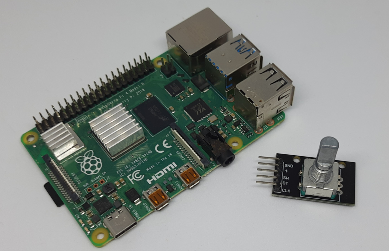
As usual, I suggest adding from now to your favourite e-commerce shopping cart all the needed hardware, so that at the end you will be able to evaluate overall costs and decide if to continue with the project or remove them from the shopping cart. So, hardware will be only:
- Raspberry PI Computer Board (including proper power supply or using a smartphone micro USB charger with at least 3A)
- high speed micro SD card (at least 16 GB, at least class 10)
- Dupont wirings
- Incremental Rotary Encoder (like KY-040 or HW-040)
Step-by-Step Procedure
Wire the Incremental Rotary Encoder with Raspberry PI
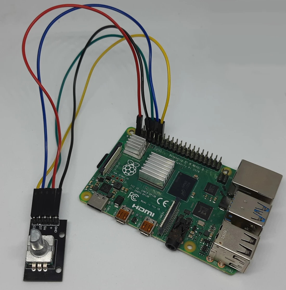
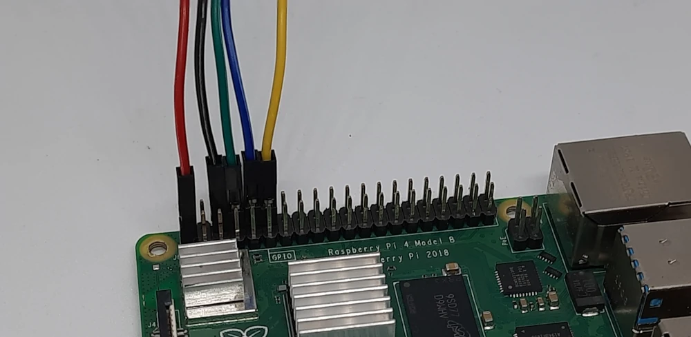
First of all, please connect the device to your Raspberry PI computer board according to the following schema. You can refer to my Raspberry PI Pinout tutorial to see the PIN meanings.

Some pictures from my lab follow:
Preparing the Raspberry PI Operating System
The first step is installing the Operating System. You can install the Raspberry PI OS Lite to get a fast and light operating system (headless). In this case, you will need to work from a remote SSH terminal. If you need a desktop environment, you can also use the Raspberry PI OS Desktop, in this case working from its terminal app. The links provide you the procedures for both the OSs. Please find the differences between the 2 OS versions in my Raspberry PI OS Lite vs Desktop article.
Make sure that your system is up to date. Connect via SSH terminal and type the following command:
sudo apt update -y && sudo apt upgrade -yChecking the Incremental Rotary Encoder Map
From what I can see, the market offers many “Rotary Encoders”, each one appearing the same but bringing different hardware and working in different ways.
For this reason, I prepared a small script which enables you to check what your module outputs at each rotation and adapt the main code to your hardware.
The script will allow you to check the signals from the clk and dt PINs at encoder rotations and map them to a list variable. You can download this Python script in your Raspberry PI with the following terminal command:
wget https://peppe8o.com/download/python/rotary/inc_rot_pi_map.pyIncremental Rotary Encoder Map Code
The following lines will explain the code line by line. At this stage we don’t map the SW button as it just works as a simple button. So, we’ll map only the CLK and DT PINs.
At the beginning, we import the InputDevice module:
from gpiozero import InputDeviceThen, we define the required variables. The clk_pin and dt_pin will get the (Broadcom) PIN numbering. According to my wiring schema, they are the 18 and 15 PINs. Then we initialize the related InputDevice objects:
clk_pin = 18
dt_pin = 15

clk_obj = InputDevice(clk_pin)
dt_obj = InputDevice(dt_pin)
The clk_val_prev and dt_val_prev variables will store the related PINs value so that we can detect when DT and CLK values change:
clk_val_prev = clk_obj.value
dt_val_prev = dt_obj.value
The main loop starts by reading the PINs current values:
try:
  while True:
    clk = clk_obj.value
    dt = dt_obj.value
With the following “IF” statement, if the code detects that one of the PINs has changes its state it prints the resulting combination:
    if clk!=clk_val_prev or dt!=dt_val_prev:
        print(clk,", ",dt)
After this, the clk_val_prev and dt_val_prev are updated, so that at the next loop we’ll be able to detect when something changes again:
    clk_val_prev = clk
    dt_val_prev = dt
The final “except” statement will catch interrupt signals sent from the terminal, closing the script. This means that you will be able to close the script at any time by pressing CTRL+C:
except KeyboardInterrupt:
    quit()
Run the Mapping Code
At this point, you can run this script from your Raspberry PI by issuing the following command:
python3 inc_rot_pi_map.pyBy rotating the shaft of a “click” clockwise, you will see your terminal showing 4 lines with the detected values.
You can stop the script.
For example, in my case:
pi@raspberrypi:~ $ python3 inc_rot_pi_map.py
1 ,  0
0 ,  0
0 ,  1
1 ,  1
Please note this sequence in a notepad starting from the first line to the end. You should also insert it in a series of square parentheses as shown in the following:
[[1, 0][0, 0][0, 1][1, 1]]Mark this row as “ClockWise”.
Now, please repeat the test by running again the same script, this time rotating the shaft counterclockwise. You should get something similar to the following:
pi@raspberrypi:~ $ python3 inc_rot_pi_map.py
0 ,  1
0 ,  0
1 ,  0
1 ,  1
Similarly, the new list object will be:
[[0, 1][0, 0][1, 0][1, 1]]Mark this row as “CounterClockWise”.
You can now move to the following script.
Incremental Rotary Encoder with Raspberry PI: Usage Script
Please download the following script in your Raspberry PI with the following terminal command:
wget https://peppe8o.com/download/python/rotary/inc_rot_pi.pyThe Rotary Encoder Usage Script
In this chapter, I will explain the code line by line and show you where to customize the script if you get different results from the previous tests.
At the beginning, we’ll import the required libraries:
from gpiozero import Button, InputDevice
import threading
The following lines will store the PIN numbers (so that you can change them here if you need to change the wiring) and initialize the PIN objects. Please note that, for the switch button, we use the “Button” object coming from the GPIOZero built-in library for Raspberry PI:
clk_pin = 18
dt_pin = 15
sw_pin = 14

clk_obj = InputDevice(clk_pin)
dt_obj = InputDevice(dt_pin)
sw_obj = Button(sw_pin)
The following lines will store the ClockWise path (“cw_path”) and CounterClockWise path (“ccw_path”) obtained from the previous tests. Please change the values if you get different results compared to mine:
cw_path = [[0, 1], [1, 1], [1, 0], [0, 0]]
ccw_path = [[1, 0], [1, 1], [0, 1], [0, 0]]
The code also stores a “counter” variable. This will count how many steps are detected from the shaft rotations:
counter = 0The first custom function now comes: the button_pressed. Inside this function you can write any action to take when you press the shaft button. In this case, I just set it to reset the counter (we must use the “global” statement to modify a variable available from the main program inside a function):
def button_pressed():
    global counter
    counter = 0
    print("Reset counter. New value: ",counter)
    return True
Here comes the most important custom function that increases and decreases the counter at any shaft step: the check_rotation. This function will run in a parallel sequence (thread) together with the main program.
At the beginning of this function, we call all the required variables from the main program. We also initialize a “rot_log” list object, which will store all the most recent signals received from the CLK and DT PINs. Moreover, we call a “stop_threads” variable (we’ll see this variable later in the code): this will allow us to close the parallel threading that we’ll use to detect the rotations. Similarly to the mapping script, we’ll also store the “clk_val_prev” and “dt_val_prev” values:
def check_rotation():
    global last_log
    rot_log=[[1, 1]]
    global cw_path
    global ccw_path
    global counter
    clk_val_prev = clk_obj.value
    dt_val_prev = dt_obj.value
    global stop_threads
The main loop will run indefinitely in the parallel thread until the “stop_threads” variable will not be set to 1:
while not stop_threads:At the beginning of every loop, we’ll check the CLK and DT values:
       clk = clk_obj.value
       dt = dt_obj.value
The first “IF” statement will check if at least one of the CLK or DT PINs has changed its value. If not, the program will restart a new loop. Otherwise, it will run the following checks, starting from storing the current values in the “last_log” variable:
       if clk!=clk_val_prev or dt!=dt_val_prev:
           last_log = [clk_obj.value, dt_obj.value]
If any PIN changes, the code will perform a first check by verifying if the “last_log” value is different from the last couple stored in the rot_log ( “rot_log[len(rot_log)-1]”).
In this case, we’ll append the recorded values at the end of the “rot_log” variable.
Then, we’ll make sure that the “rot_log” always remains within a limited length (to avoid casting the memory used by our program). We’ll use the length of the “cw_path” object as the maximum length for the “rot_log”:
           if last_log != rot_log[len(rot_log)-1]:
              rot_log.append(last_log)
              rot_log=rot_log[-len(cw_path):]
Now, we can update the “counter” value if required. If the rot_log matches the cw_path, we’ll increase it. If the rot_log matches the ccw_path, we’ll decrease it:
           if rot_log == cw_path:
              counter += 1
           if rot_log == ccw_path:
              counter -= 1
The following lines will update the clk_val_prev and dt_val_prev when the program enters the first “IF” statement of this function:
           clk_val_prev = clk
           dt_val_prev = dt
Now that the job running the update of the rotation counter is completed, we can care again for the main program.
Before running the main loop, which will show you the counter updates, the code will create a parallel thread for the “check_rotation” function and start it. As described before, the “stop_threads” variable used to kill the thread is initialized to 0:
stop_threads = 0
t1 = threading.Thread(target=check_rotation, name='t1')
t1.start()
We also use another parallel handler to manage the event of shaft pressing. For this, we’ll use the built-in “when_pressed” method of the “Button” object. When this event occurs, the code will run the “button_pressed” function already described:
sw_obj.when_pressed = button_pressedWe’ll also initialize an “cnt_old” variable: it will store the counter values at each loop, so that we can detect when the counter variable changes:
cnt_old = counterFor this project, the main loop is very simple: it will check changes from the counter value, printing it when a change occurs. An initial “try” statement will also help us to detect interrupt signals from the user so that we can correctly manage the program closing:
try:
   while True:
       if counter != cnt_old:
          print(counter)
          cnt_old = counter
The last lines will catch when you’ll press the CTRL+C from your terminal, by setting the “stop_threads” variable to 1, besides printing some courtesy info to your terminal. This variable will close the rotary encoder thread:
except KeyboardInterrupt:
   print("Stopping the rotary encorer threads")
   stop_threads = 1
   print("Ended")
Use the Incremental Rotary Encoder with Raspberry PI
At this point, we’re ready to use the Rotary Encoder. From your terminal, please issue the following command:
python3 inc_rot_pi.pyYou can now rotate the shaft clockwise and counterclockwise, besides pressing it. It will return something similar to the following:
pi@raspberrypi:~ $ python3 inc_rot_pi.py
1
2
3
4
3
2
1
0
-1
-2
-3
-4
-5
Reset counter. New value:  0
0
1
You may see that some steps aren’t detected by the program. This should not be an issue for classic usage of the device and, in any case, you can reset the counter value by pressing the shaft.
What’s Next
If you want to discover many other projects for your Raspberry PI, you can take a look at peppe8o Raspberry PI tutorials.
Enjoy!

Open source and Raspberry PI lover, writes tutorials for beginners since 2019. He's an ICT expert, with a strong experience in supporting medium to big companies and public administrations to manage their ICT infrastructures. He's supporting the Italian public administration in digital transformation projects.
![]()
![]()
![]()
![]()
![]()
![]()
![]()