
Last Updated on 2nd September 2023 by peppe8o
In this tutorial, I will show you how to measure the Raspberry PI Pico power consumption (in mA) and I will report the ones I’ve measured.
Running IoT projects without a line power supply requires identifying your power budget in order to avoid service outages due to missing power. For this reason, measuring the Raspberry PI Pico W power consumption will help to understand if your battery or solar cells have the right dimensioning.
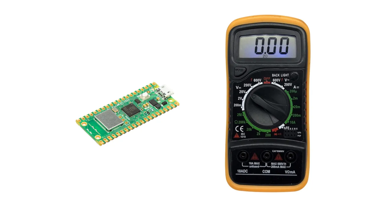
For this scope, I used a Digital Multimeter. I will show you the wiring diagram in order to use correctly this tool and I will show you the measures that I got with different tests on different MicroPython codes. This is a useful exercise when you need powering the Raspberry PI Pico from external batteries or powering Raspberry PI Pico with solar cells.
I also use an external 18650 battery to perform my test, as there’s no un-invasive way to put the digital multimeter in series with the micro USB port of our Raspberry PI Pico. On the other hand, this means that we need to save our MicroPython test code as “main.py” in our Raspberry PI Pico storage in order to get this run automatically at the Pico boot. Moreover, please remember to avoid keeping connected at the same time both the external battery and the micro USB. To perform this, you will need to add a Schottky diode to the battery in order to protect it from the current flowing back (please refer to my powering the Raspberry PI Pico from external batteries tutorial for more details).
Finally, I will show you a few tricks to reduce the Raspberry PI Pico W power consumption.
Digital Multimeters
A digital multimeter is a cheap but essential tool for any electrician or technician. It can measure electrical properties such as voltage, current, and resistance. Newest and more advanced digital multimeters can also test continuity, capacitance, and temperature.
When choosing the right digital multimeter, please take care of checking what is the supported range, in order to have it compliant with the measurements you want to perform. With our Raspberry PI Pico current dimensions, a multimeter able to measure more than 400 mA would be the better solution, even if I will use a trick to perform my tests with a 200 mA digital multimeter.
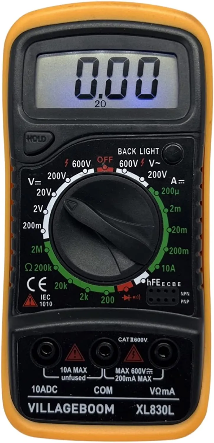
Digital Multimeter Ports
Before running our tests, it can be helpful to understand how to connect the digital multimeter to any circuit correctly. Usually, these tools have 3 ports.
The COM port is the common negative pole and can be wired with the device’s black end. The device’s red end should be connected to one of the 2 remaining ports.
Usually, the “fused” one allows one to perform more precise measurements in milli-amperes or voltage, but it can support only low amperage/voltage. On the other hand, the “unfused” one allows us to deal with far higher amperage, but at the cost of far lower precision.
For our tests, we’re going to use the COM and the fused ports.
Digital Multimeter Connections
The Digital Multimeter connections change based on the kind of measurement we want to perform.
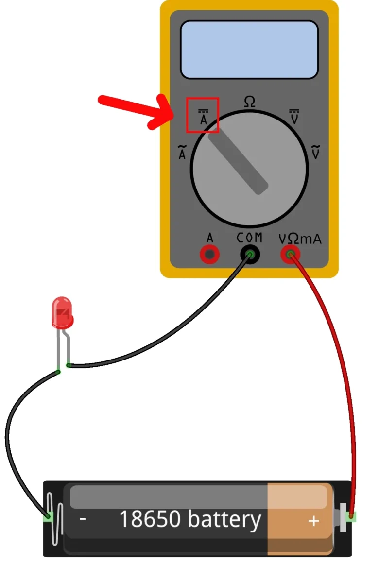
An Ampere measurement requires that the current flow in your multimeter (properly set). This means that by setting the multimeter to test the Amperes, its internal circuit sets the internal resistor to a very low value, enabling the current to flow in it by reducing the voltage loss according to the Ohm law.
As we’re going to measure low (mA) current, we’ll use the V/Ohm/mA port.
In this case, the correct wiring is similar to the following, also known as a series connection:
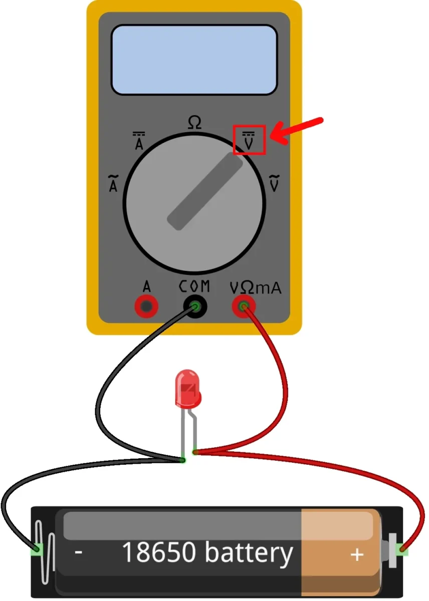
An Voltage measurement requires that the current NOT flow in your multimeter (properly set), otherwise it would affect the measurement according to the Ohm law. This means that by setting the multimeter to test the Voltage measurement, its internal circuit set the internal resistor to a very high value. In this case, the correct wiring is similar to the following, also known as a parallel connection:
Measuring Power Consumption with Ampere
A digital multimeter is a versatile and accurate device that can measure current in milli-Amperes (mA). The power consumption is usually defined in milli-Amperes-hour (mAh), which is the quantity of current flowing multiplied by the flowing time (in hours).
This means, by the way, that 1 mA flowing for 1 hour (3.600 seconds) will consume 1 mAh. Similarly, a circuit using 3.600 mA for 1 second and 0 (zero) mA for the remaining 3.599 seconds will have the same power consumption, 1 mAh.
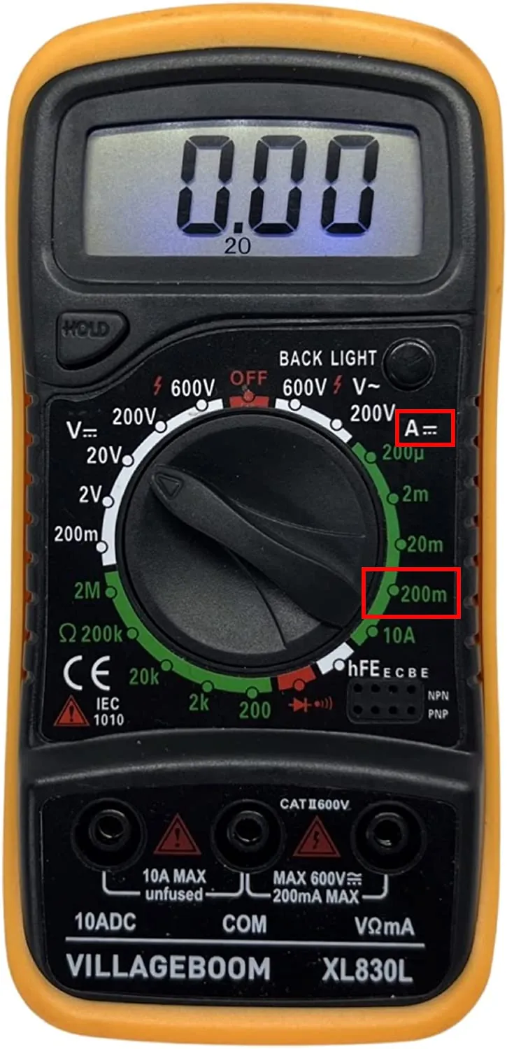
To perform this task you will need to set the multimeter to the DC Ampere setting, selecting the desired range. This is usually done by turning the dial to the mA setting or pressing the mA button (please refer to your digital multimeter user manual):
Once the multimeter is set to the mA setting, you will need to connect the multimeter to the circuit you are testing, and then take a reading. To do this, press the “measure” button on the multimeter.
The display will show the current in milli Amperes (mA). It is important to note that the multimeter should be set to the correct range before taking a reading. If the current is too high, the multimeter may not be able to accurately measure it.
Using a digital multimeter to measure current in milli Amperes (mA) is a simple and effective way to test electrical circuits. With the right knowledge and practice, anyone can use a digital multimeter to measure current in milli Amperes (mA).
What We Need
As usual, I suggest adding from now to your favourite e-commerce shopping cart all the needed hardware, so that at the end you will be able to evaluate overall costs and decide if to continue with the project or remove them from the shopping cart. So, hardware will be only:
- A common computer (maybe with Windows, Linux or Mac). It can also be a Raspberry PI Computer board
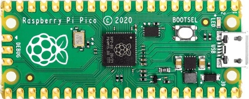
- Raspberry PI Pico microcontroller (with a common micro USB cable)
- Digital Multimeter
- 18650 battery with 18650 case
- breadboard (optional)
- dupont wirings
Step-by-Step Procedure
Prepare the Wiring to test Raspberry PI Pico W Power Consumption
Please check that your Digital Multimeter is set to the correct DC Amperometer settings.
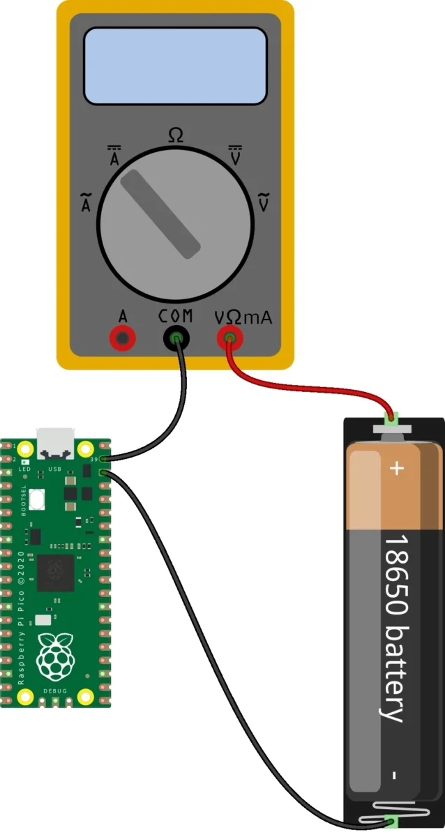
As we’re going to measure the Ampere to check Raspberry PI Pico W power consumption, our series connection will use the schema according to the following picture:
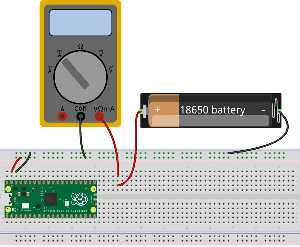
If you prefer to set the wiring with the help of a breadboard, the diagram will be like the following:
Prepare the MicroPython code
Prepare the Raspberry PI Pico MicroPython firmware according to my First steps with Raspberry PI Pico for Beginners. In the following chapters, I will show you the code to save as “main.py” in your Raspberry PI Pico storage.
It is also important to note that the new firmware for Raspberry PI Pico W names the on-board LED differently from the “old” Raspberry PI Pico (without W).
With the Raspberry PI Pico W MicroPython firmware, the LED will be referred to with this line:
led = Pin("LED", Pin.OUT)while the Raspberry PI Pico (without “W”) MicroPython firmware, the same line will become:
led = Pin(25, Pin.OUT)To perform the tests, please use the following procedure:
- Plug the micro USB between Raspberry PI Pico and the computer with Thonny
- Upload the MicroPython code to your main.py file in your Raspberry PI Pico storage
- Un-plug the micro USB cable
- Connect the battery to your circuit
- Check the measurements
- Disconnect the battery
- plug the micro USB cable for code editing needs
Test 1: Raspberry PI Pico W power consumption blinking built-in LED
In this test, we’ll check how much current the Raspberry PI Pico W uses by doing… nothing than switching on and off its built-in LED. We’ll compare the measures when the LED is on and when it is off. The MicroPython code is the following, where the timer frequency sets how many times the led will toggle in 1 second (0.2 means 1 time every 5 seconds):
from machine import Pin, Timer
led = Pin('LED', Pin.OUT)
timer = Timer()

def blink(timer):
    led.toggle()

timer.init(freq=0.2, mode=Timer.PERIODIC, callback=blink)
The results I’ve measured in my digital multimeter are:
- LED off: 38 mA
- LED on: 41 mA
This means that the Pico running just for the MicroPython code uses around 38 mA, while powering on the built-in LED requires around 3 mA in addition.
Test 2: Raspberry PI Pico W power consumption with WiFi (with WiFi power saving mode)
In this test, I will wait for the WiFi to connect and check how much additional power is required from the WiFi module. Please note that usually the WiFi uses more or less power depending on the distance from the wireless router, so this value can change accordingly to your physical distance.
Additional note, by default the Raspberry PI Pico W MicroPython firmware enables the WiFi with a “power saving mode”. The code to perform this test follows, where you need to adjust your 2-letters country code, your WiFi SSID and password.
from machine import Pin
import network, rp2, time

# set your WiFi
rp2.country('IT')

wlan = network.WLAN(network.STA_IF)
wlan.active(True)

wlan.connect('Your_SSID', 'Your_WiFi_Password')

while not wlan.isconnected() and wlan.status() >= 0:
    print("Waiting to connect:")
    time.sleep(1)
Once connected to the battery, I will check that the RPI Pico is connected to my WiFi by looking at my router clients and with a ping test.
Here the 200mA limit of my digital multimeter raised, as I realised that when the Raspberry PI Pico W performs the WiFi connection it uses more than 200 mA. This was bringing my digital multimeter out of scale, so cutting the power and preventing my Pico from completing the process. The workaround has been using a wire bridge that allows the current to bypass the multimeter when the Raspberry PI Pico W sets the WiFi connection (the yellow wire in the following picture):
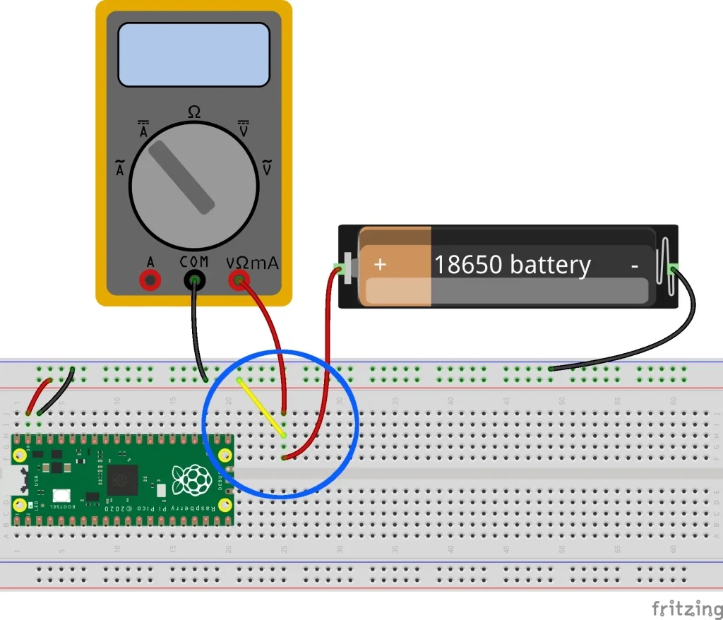
During this setup, the digital multimeter will show a very low current value, as the current will flow quite all from the yellow wire, which will result in the less resistive path for the current.
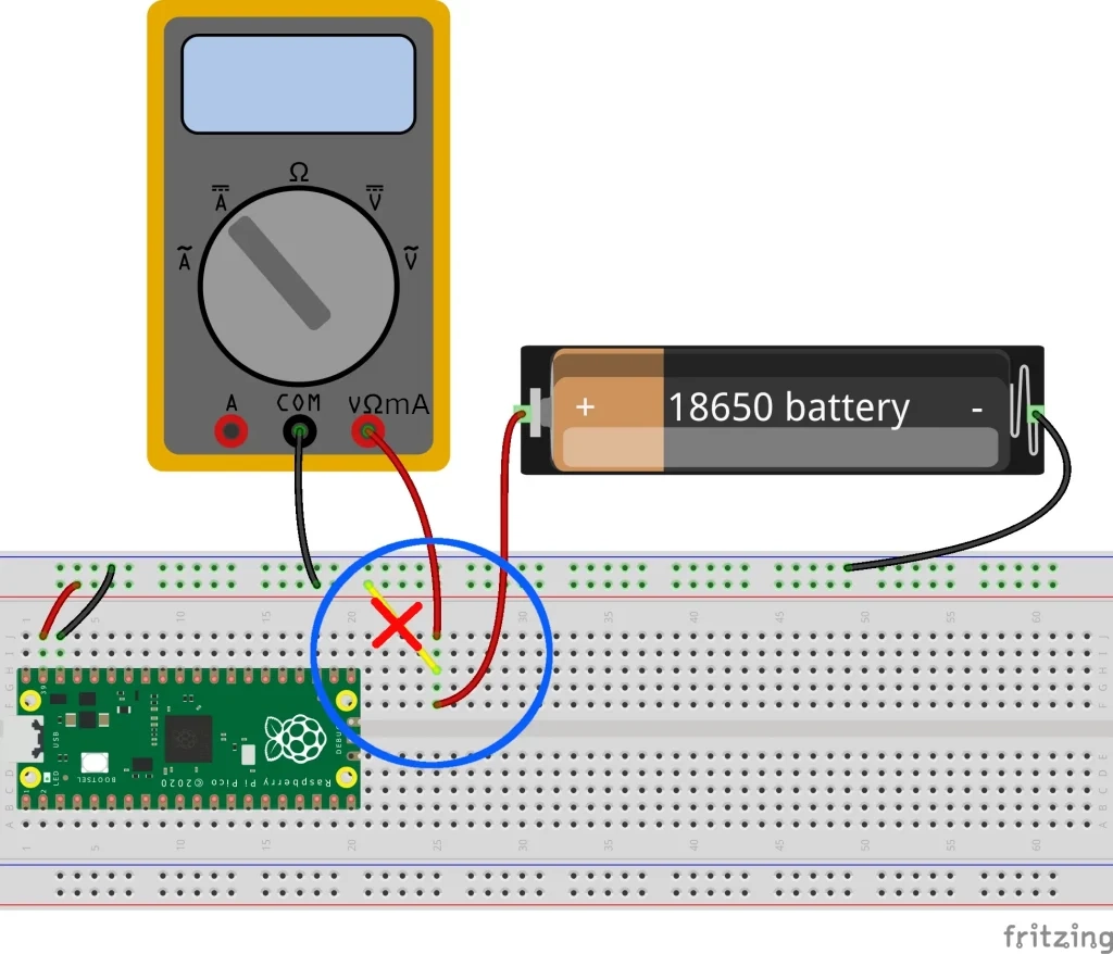
Once the Raspberry PI Pico W was connected to my WiFi network, I was able to check it both from my router clients list and from the Pico answering my ping requests from a remote computer. At this point, we can remove the bypass wire and get the correct measurement shown in our digital multimeter:
Here are the Raspberry PI Pico power consumption results:
- WiFi connected: 43 mA
- WiFi connected and answering remote ping requests: around 60mA
This means that, with WiFi power-saving mode, the additional power is really low as 5mA (remember, my tests have been performed at around 3 meters from my WiFi router and the distance can affect this value).
Test 3: Raspberry PI Pico W power consumption with WiFi (withOUT WiFi power saving mode)
Now, let’s try removing the power-saving mode from our MicroPython code. This can be get by explicitly setting “wlan.config(pm = 0xa11140)” as in the following code:
from machine import Pin
import network, rp2, time

# set your WiFi
rp2.country('IT')
wlan = network.WLAN(network.STA_IF)
wlan.active(True)

# set power mode to get WiFi power-saving off (if needed)
wlan.config(pm = 0xa11140)

wlan.connect('Your_SSID', 'Your_WiFi_Password')

while not wlan.isconnected() and wlan.status() >= 0:
    print("Waiting to connect:")
    time.sleep(1)
Of course, the same trick has been required in order to avoid my digital multimeter limit of 200mA during the WiFi connection setup. The result:
- WiFi (power-saving mode DISABLED): 72 mA (same value also during ping requests)
Test 4: Raspberry PI Pico W power consumption with a While Loop
In this test, I will give my Raspberry PI Pico W something to do while I will check the power consumption. The job will be just running a simple while loop without any specific computing task. The code will also give a visual warning to the user that the task has started with the built-in LED. At the program start it will switch on for 2 seconds and then turn off. After this, the measurement will start:
from machine import Pin
import time
led = Pin('LED', Pin.OUT)

led.value(1) # LED ON warning that the program is running
time.sleep(2)
led.value(0) # LED OFF warning that measurement can now be done

while True:
    pass
The test result:
- while loop: 43 mA
Test 5: Raspberry PI Pico W power consumption with a For Loop
The other common loop in MicroPython is the FOR loop. In this case, I will make this loop running along with a variable (“i”) increasing at each loop run. Again, the built-in LED will help with a visual notification when the test measurements can start:
from machine import Pin
import time
led = Pin('LED', Pin.OUT)

led.value(1) # LED ON warning that the program is running
time.sleep(2)
led.value(0) # LED OFF warning that measurement can now be done

for i in range(0, 10000000):
    pass

led.value(1) # LED ON warning that the test finished
This test got a Raspberry PI Pico W power consumption equal to the previous test:
- for loop: 43 mA
Reducing Raspberry PI Pico W Power Consumption
In this chapter, I’ve performed a few tests to check how the Raspberry PI Pico W power consumption can be reduced and how much we can save.
Test 1: Reduce Raspberry PI Pico W power consumption with time.sleep
The first test is to check if the time.sleep() function from MicroPython can give us any benefits. The following code will use the time.sleep() for 5 seconds:
from machine import Pin
import time
led = Pin('LED', Pin.OUT)

led.value(1) # LED ON warning that the program is running
time.sleep(2)
led.value(0) # LED OFF warning that measurement can now be done

time.sleep(5)

led.value(1) # LED ON warning that the test finished
The result of this test is that the time.sleep() function is just to make time to pass… as it didn’t reduce our amperage:
- sleep test: 39 mA
Test 2: Reduce Raspberry PI Pico W power consumption with machine.deepsleep()
The machine.deepsleep() is a kind of different command and really useful to save batteries.
it is important to understand that the deepsleep() command will break all the active connections and make your Raspberry PI Pico W in something like a standby mode. In this period you can’t connect and/or stop the microcontroller without cutting the power. For this reason, I’ve increased the time.sleep() in the setup phase to 10 seconds, in order to give you the ability to stop this main.py program from Thonny after the test is finished and the Pico comes back to the computer connection.
The standby period is expressed in milliseconds. After this period, the Raspberry PI Pico W will reset and start again your main.py program from the beginning.
from machine import Pin
import time
led = Pin('LED', Pin.OUT)

led.value(1) # LED ON warning that the program is running
# Here I added more sleep time in order to recover the Pico in this time frame after the test ends
time.sleep(10)
led.value(0) # LED OFF warning that measurement can now be done

machine.deepsleep(5000)
This time, we get an excellent power reduction:
- deepsleep test: 16 mA
Test 3: Reduce Raspberry PI Pico W power consumption Changing CPU Frequency
The Raspberry PI Pico W has a CPU frequency, set by default to 125MHz in MicroPython, that can be changed to give us the opportunity to reduce performance and save power. We can use the machine.freq() command without variables to get the current value:
>>> %Run -c $EDITOR_CONTENT
>>> machine.freq()
125000000
The same command allows us to express the frequency to set, by putting the Hz value as input.
Theoretically, the Raspberry PI Pico W can run at a minimum of 2 kHz. From a practical point of view, at least with MicroPython, I’ve experienced that setting CPU frequency values lower than 20MHz will return the following error:
>>> %Run -c $EDITOR_CONTENT
Traceback (most recent call last):
  File "<stdin>", line 10, in <module>
ValueError: cannot change frequency
For this reason, my test will check the power consumption at the lowest value acceptable from MicroPython. I will use a 5 seconds time frame to check the measurements, before restoring the CPU frequency to my default:
from machine import Pin
import time
led = Pin('LED', Pin.OUT)

led.value(1) # LED ON warning that the program is running
time.sleep(2)
led.value(0) # LED OFF warning that measurement can now be done

machine.freq(20000000) # reduce to 20MHz
time.sleep(5)
machine.freq(125000000) # restore to 125MHz

led.value(1) # LED ON warning that the test finished
This test shows a good power saving, even keeping the Pico always ready and operating:
- frequency test: 30 mA
Summarizing the tests
Please find below a table showing a summary of the previous tests:
| Test | Power Consumption |
|---|---|
| Power on (no tasks) | 38 mA |
| built-in LED on | 41 mA |
| WiFi (power-saving mode) | 43 mA |
| WiFi + ping (power-saving mode) | 60mA |
| WiFi (power-saving DISABLED) | 72 mA |
| WiFi + ping (power-saving DISABLED) | 72 mA |
| WHILE loop | 43 mA |
| FOR loop | 43 mA |
| time.sleep() | 39 mA |
| machine.deepsleep() | 16 mA |
| CPU Freq reduced to 20MHz | 30 mA |
What’s Next
Interested in doing more with your Raspberry PI Pico? Try to look at my Raspberry PI Pico tutorials for useful and funny projects!
Enjoy!

Open source and Raspberry PI lover, writes tutorials for beginners since 2019. He's an ICT expert, with a strong experience in supporting medium to big companies and public administrations to manage their ICT infrastructures. He's supporting the Italian public administration in digital transformation projects.
![]()
![]()
![]()
![]()
![]()
![]()
![]()

Would be interesting to see this mode: Vcc 1.8V, freq. 20Mhz (🫤MicroPython), deep sleep.
This is dangerous. You should not connect any battery directly to an LED without a resistor, especially a lithium battery…
Hi Daniel. The first images are just examples to understand how a multimeter works. Even if it has a resistance, you are right that in a real case a resistor should be connected in series with the LED
Your pic with the batttery, led and multimeter on ‘amps’ range will burn the led or blow the fuse in the multimeter
You are right, the LED setup is just an example to show how a multimeter works. I’ll update the pictures with a more generic load and source. Many thanks for your feedback