
Last Updated on 13th April 2024 by peppe8o
In this tutorial, I will show you how to power a Raspberry PI Pico with Solar Cells. Moreover, I will also include an external battery as a backup power supply for the moments when light is unavailable.
Raspberry PI Pico and, even more, the Pico W model are excellent devices for IoT projects. Where the power supply is hard to find, powering the Raspberry PI Pico with a solar cell may give you the ability to make your project flexible enough for deploying it in remote zones.
Something similar is described in my Powering the Raspberry PI Pico from External Batteries tutorial, where I’ve shown how the internal power circuits in Raspberry PI Pico are composed and what PINs to use to power our microcontroller. I suggest you to read it, as it makes clear this basis.
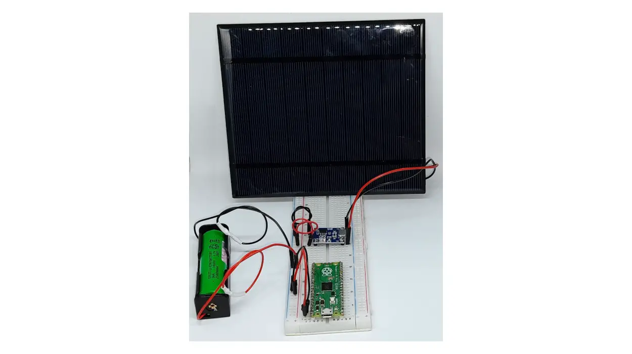
Before going to the wirings, let’s take a closer look at the pieces used in my small lab.
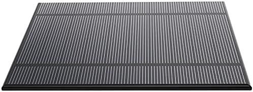
The Solar Cells
A solar cell, or photovoltaic cell, is an electronic device that converts the energy of light directly into electricity by the photovoltaic effect, which is a physical and chemical phenomenon (ref. wikipedia.org). I’m not going to describe in detail how solar cells work, as the web is full of web pages able to do this job better than me. For the sake of this tutorial, what is important to understand is the measures coming from their datasheet.
All solar cells come with a definition of their capacity to provide energy from the sun, usually measured in the best case. the producers usually provide at least 2 between the following 3 items:
- the peak Voltage capacity
- the peak Watt capacity
- the peak Ampere capacity
Those measures are linked by the well-known Ohm law: Power [Watt] = Voltage [Volt] x Current [Ampere]. For this reason, knowing 2 of these will always let us get the third one.
When choosing the solar cell for our projects, we must pay attention to the cell capacity: different production processes and materials can bring different cell efficiencies. Because I’m going to connect my Raspberry PI Pico with the solar cell by the TP4056 module, which we’ll see in the following paragraphs, I looked for a solar cell able to provide at least 5V with a decent power output. One that I found interesting comes from the ALLPOWERS and has the following peak values:
- V = 5V
- C = 500mA
- P = 2,5W
There are many solar cells in the market available at affordable costs that you can evaluate, but take always care of these parameters in order to get a decent solar power input. At a fixed voltage input, the higher the current will give you a faster battery recharge.
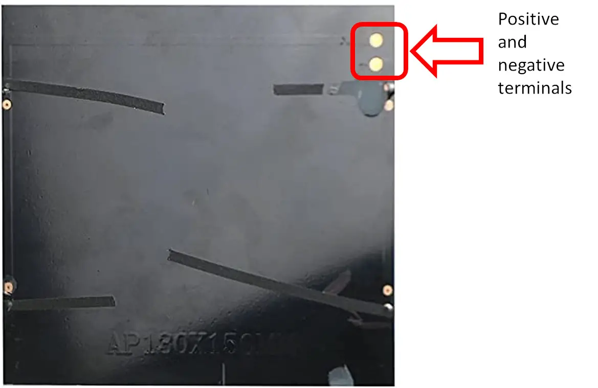
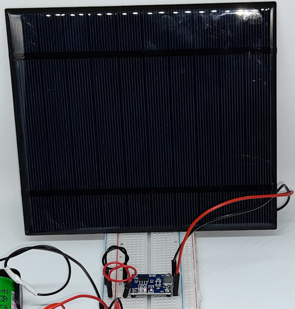
Usually, the solar cells are sold without the wiring, having only the 2 terminals (positive and negative in their back to be soldered with your wires:
Many times these solar panels are sold in multiple packages. When the current provided by a cell is not enough for your project, you can connect more cells in parallel (to get higher current) or in series (to get higher voltage) in order to fit your needs. Or you can use a mixed schema, so getting the benefits from both of the connections, depending on the number of cells you get.
Also consider that, depending on the place where your project resides, you could get more light or less light. the combination of the solar cells will give you enough room to fit your power budget.
The 18650 Battery
When the sun is out, our Raspberry PI Pico and the solar cell will not work. For this reason, I’ve planned this tutorial already including a power backup with a 18650 battery. This kind of battery is not a new format in the market. You can find a lot of these on whatever e-commerce website at very affordable prices. Differently from the AA and the AAA I’ve used in my Powering the Raspberry PI Pico from External Batteries tutorial, this format has a bit higher sizes, but it can assure higher voltage (3,7V) and a longer capacity (usually more than 3000mAh). It is important to understand this value: 3000mAh means that it can provide 3000 mA for 1 hour or 300 mA for 10 hours or 100 mA for 30 hours and so on. This is important as in your projects you will need, sooner or later, to calculate your power drain budget based on the devices attacked to your Raspberry PI Pico. And you will need to make this complaint with the current that you collect from the solar cells and what you can store in your power backup system (this battery, in our case).

Please remember that you will need to get a rechargeable 18650 battery.
From the e-commerce stores, you can also get the cases fitted to store the 18650 battery. This is really useful as it allows you to avoid soldering the wires directly on the battery and/or attaching them with tape. Another DIY solution, for people owning a 3D printer, is also getting a 18650 case design from sites like thingiverse and creating it by yourself.
The TP4056 module
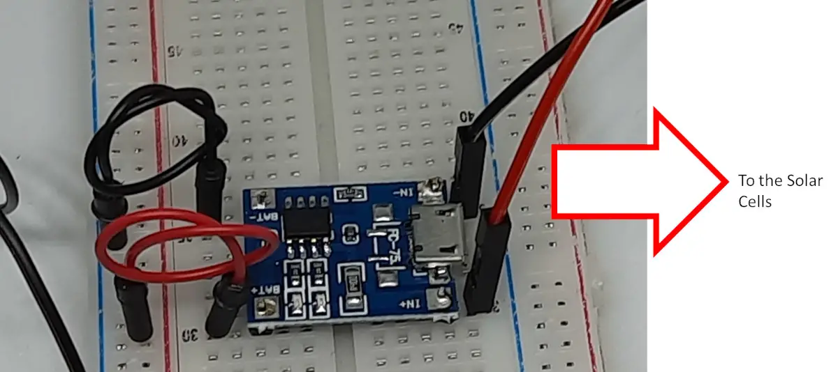
This is an important part of my assembly, still available at a very affordable price. This is a battery charger module. It includes all the circuits required to protect your battery while recharging and avoiding the current from coming back to the power source once the battery has reached a higher level compared to the power source.
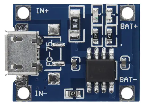
This module is specifically designed to be used to charge the 18650 Lithium-ion batteries, so it will work out of the box with this kind of battery. Moreover, for other load combinations, the TP4956 also includes a programmable resistor able to reduce the amperage going to battery in order to better regulate the desired output.
Looking at the main parts, it includes 2 LEDs that will visually notify if you are going to charge the battery or if this is fully charged. The BAT PINs are those connected to the battery (and to the Raspberry PI Pico), while the IN PINs will go to our solar cells.
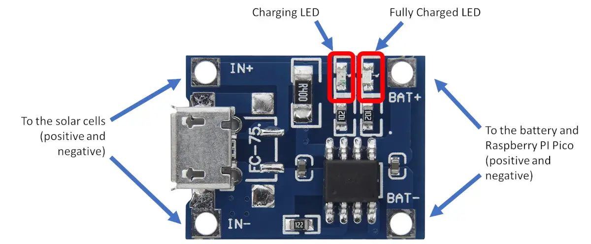
As you can see from the picture, the TP4056 also includes a micro-USB port that can be used as an alternative to our solar cell to recharge the 18650 battery.
The main features of TP4056 modules are below summarized:
| Input supply voltage | -0.3 V to 8V |
| Operating temperature range | -40°C to 85°C |
| Output Voltage | 4.2 V with 1.5% accuracy |
| Trickle charge threshold | 2.9 V |
| BAT Pin max current | 1200 mA |
Before going on
Finally, before proceeding with the project: when the battery is connected to the Raspberry PI Pico DON’T connect the PC USB cable to the Raspberry PI Pico micro USB port for programming it. Please detach the battery before connecting the PC OR use a Schottky diode to protect the battery.
What We Need
As usual, I suggest adding from now to your favourite e-commerce shopping cart all the needed hardware, so that at the end you will be able to evaluate overall costs and decide if to continue with the project or remove them from the shopping cart. So, hardware will be only:
- A common computer (maybe with Windows, Linux or Mac). It can also be a Raspberry PI Computer board
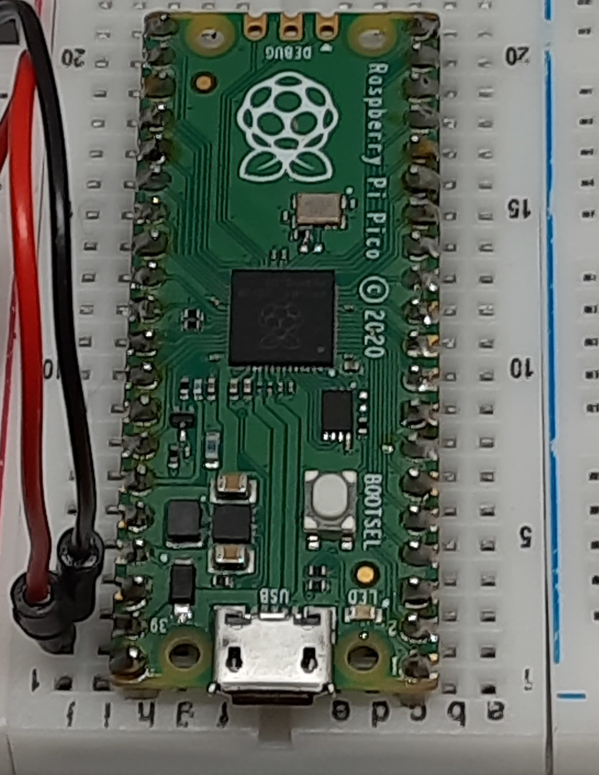
- Raspberry PI Pico microcontroller (with a common micro USB cable)
- Solar Cells
- TP4056 module
- 18650 battery with 18650 case
- breadboard (optional)
- dupont wirings
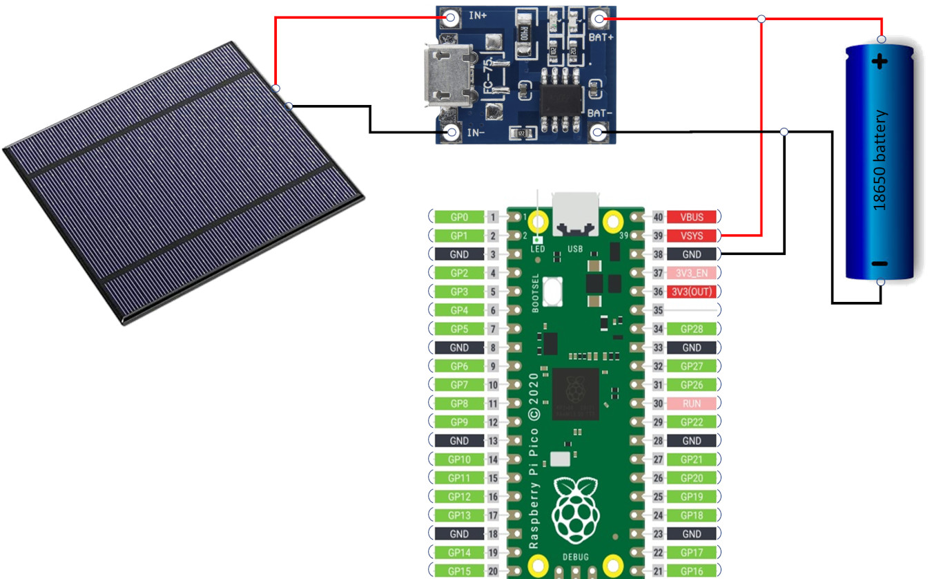
Raspberry PI Pico and Solar Cells Wiring
Please find below the wiring diagram to connect the Raspberry PI Pico with a solar cell, the TP4056 module and the 18650 battery:
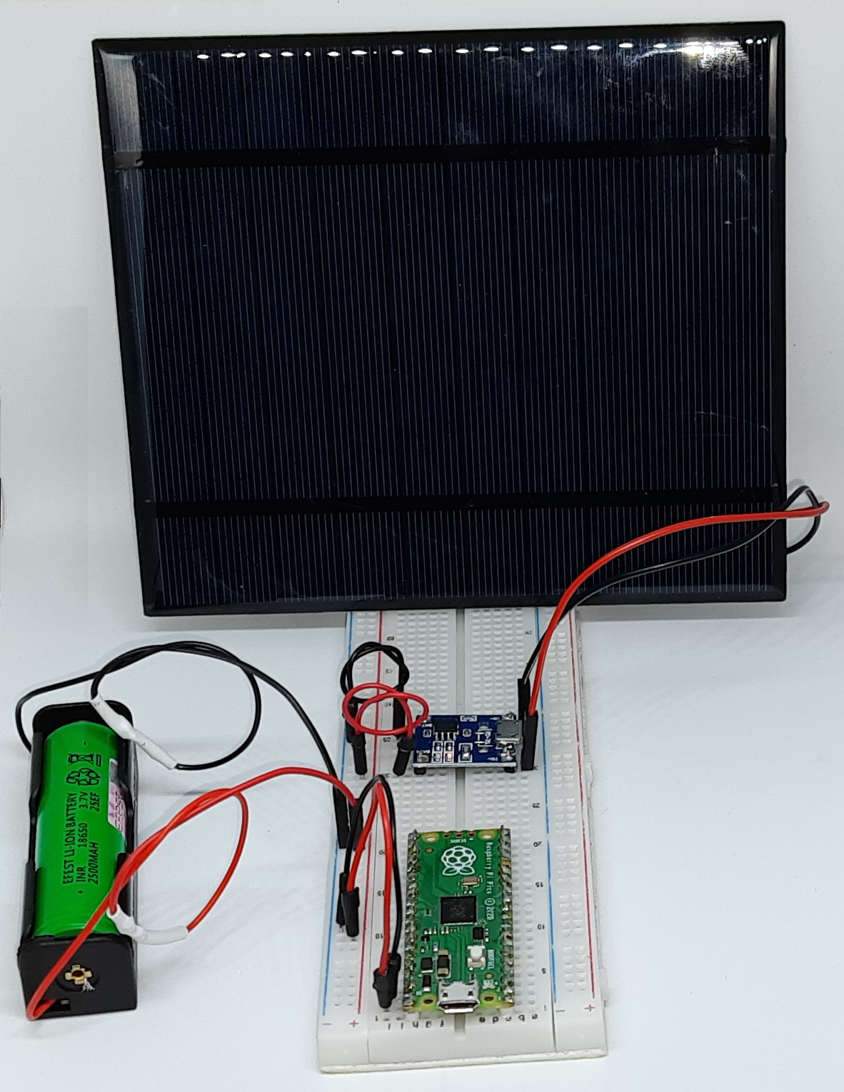
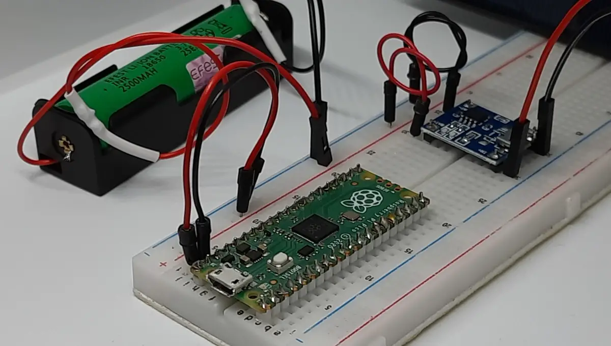
Please, find below some pictures from my lab. As you can see, I’ve used the left line running all over the breadboard length in order to wire together the TP4056 module output with the battery and the Raspberry PI Pico PIN where the microcontroller will take the power supply:
Test Raspberry PI Pico and Solar Cell
In order to test if the whole project works, please detach the Raspberry PI Pico from the power circuit and start installing the MicroPython firmware according to my First steps with Raspberry PI Pico for Beginners tutorial.
As we’ll run a code powering the RPI Pico without a PC connected, please remember to save your MicroPython code in your Raspberry PI Pico storage named “main.py”.
You can try, for example, the following blinking code, that will make the on-board LED of Raspberry PI Pico blink every half second:
from machine import Pin, Timer
led = Pin(25, Pin.OUT)
timer = Timer()

def blink(timer):
    led.toggle()

timer.init(freq=2, mode=Timer.PERIODIC, callback=blink)
Also note that the firmware for Raspberry PI Pico W addresses differently the LED port, so resulting in the following code:
from machine import Pin, Timer
led = Pin("LED", Pin.OUT)
timer = Timer()

def blink(timer):
    led.toggle()

timer.init(freq=2, mode=Timer.PERIODIC, callback=blink)
Save the code in your microcontroller storage, disconnect the RPI Pico from your PC and then connect the Raspberry PI Pico to the circuit as in the wiring diagram.
You will see the Pico on-board LED blinking.
What’s Next
Interested to do more with your Raspberry PI Pico? Try to look at my Raspberry PI Pico tutorials for useful and funny projects!
Enjoy your Raspberry PI Pico and Solar Cell projects!

Open source and Raspberry PI lover, writes tutorials for beginners since 2019. He's an ICT expert, with a strong experience in supporting medium to big companies and public administrations to manage their ICT infrastructures. He's supporting the Italian public administration in digital transformation projects.
![]()
![]()
![]()
![]()
![]()
![]()
![]()

Hi there,
I followed the same steps here as you did with this tutorial. Now I have come across an issue which I cannot explain.
I connected the wires from the TP4056 (same as yours) to the battery and the raspberry pico. To check if it works, the pico turns it own led light on.
During sunrise, the pico wont turn on unless i plug the vsys and gnd again (after plugging them out). Then the led shines a light
At sunset (when the solar panel doesn’t provide energy) the raspberry pico led light is flickering, indicating it is turning on and off again. I do not use a breadboard. Have you tried this setup for a longer time (24h)? And do you have an idea why this doesn’t work at mine?
Hi Nico, can you please try to fully charge the battery alone, connect the Pico and then removing (or covering) the solar panel? My doubt is if tour Pico and sensors use all the energy from solar panel and if there’s actually no room for battery charging
Hi, is there a way to know how much the battery is charged within the pico?
Thanks
Hi Angelo,
sorry for the late reply.
With a Pico you can measure a battery voltage (see this tutorial: Raspberry PI Pico Battery Checker), but I don’t know how much this can be realiabe as it will measure a battery voltage while from the same battery which is powering the Pico.