Last Updated on 13th April 2024 by peppe8o
This tutorial will show you how to create a Raspberry PI Pico-based battery checker and test the charge status. It also makes use of an OLED display to show the measurement results.
Checking old batteries to verify if you can still use them is a good practice to help nature and avoid trashing materials that strongly affect pollution. With Raspberry PI Pico you can check battery status and become aware if they can still work
Usually, the common 1,5V batteries can provide a 1,55V power when new (or recharged), falling down to 1,15V / 1,10V when they are quite exhausted. Some devices (like wall clocks) can use these batteries even with a lower capacity. Having a clear read of the battery capacity can help you to understand what is the current battery status and manage it accordingly.
How This Project Works
The working principle is really simple. The Raspberry PI Pico has analog PIN where you can read voltage values.
As a safety precaution, you have to pay attention to the current drain by your Pico: once you connect a battery to its PINs, it will drive current to your microcontroller. So, avoid connecting batteries with high ampere capacity to avoid your board firing. Batteries like the common AAA, alkalines and similar are safe to be tested.
Another consideration, the Raspberry PI Pico analog input can measure up to 3.3 Volts. If you need to measure higher values, you will need to add a voltage divider circuit. You can get this with just 2 resistors having proper values:
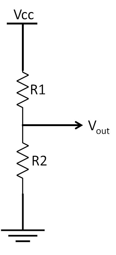
With this circuit, you can size the two resistors in such a way that the Vout (that will be connected to your Raspberry PI Pico reading PIN) will remain in a 3,3V max range. The

For example, if you want to be able to check a 9V battery, you can build this circuit using 2 resistors so that R1 value is equal to double of R2. In this way:
R2 / (R1 + R2) = R2 / (2xR2 + R2) = R2 / 3xR2 = 1/3
This means: Vout = Vcc / 3
so, the Vcc can be up to 3 times the Vout. Being Vout connected to Raspberry PI Pico PIN that is capable to read 3,3V, this ends with our Raspberry PI Pico capable to read batteries up to 9,9V attached to the Vcc.
A complete explanation of this circuit can be found at learningaboutelectronics.com: How to Reduce Voltage with Resistors.
What We Need
As usual, I suggest adding from now to your favourite e-commerce shopping cart all the needed hardware, so that at the end you will be able to evaluate overall costs and decide if to continue with the project or remove them from the shopping cart. So, hardware will be only:
- A common computer (maybe with Windows, Linux or Mac). It can also be a Raspberry PI Computer board
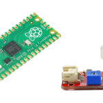
- Raspberry PI Pico microcontroller (with a common micro USB cable)
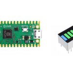
- SSD1306 OLED display (to show the battery test result)
- resistors
- breadboard
- dupont wirings
Check hardware prices with the following links:


Step-by-Step Procedure
Wiring Diagram
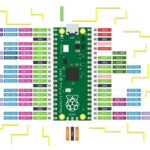
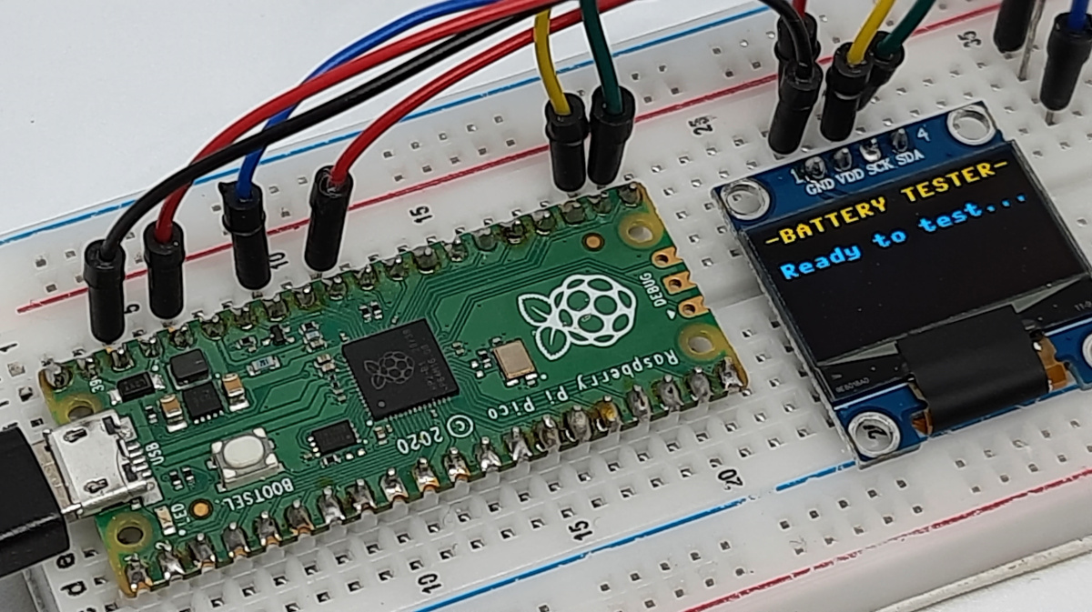
Please prepare the wiring as shown in the following picture, according to Raspberry PI Pico pinout:
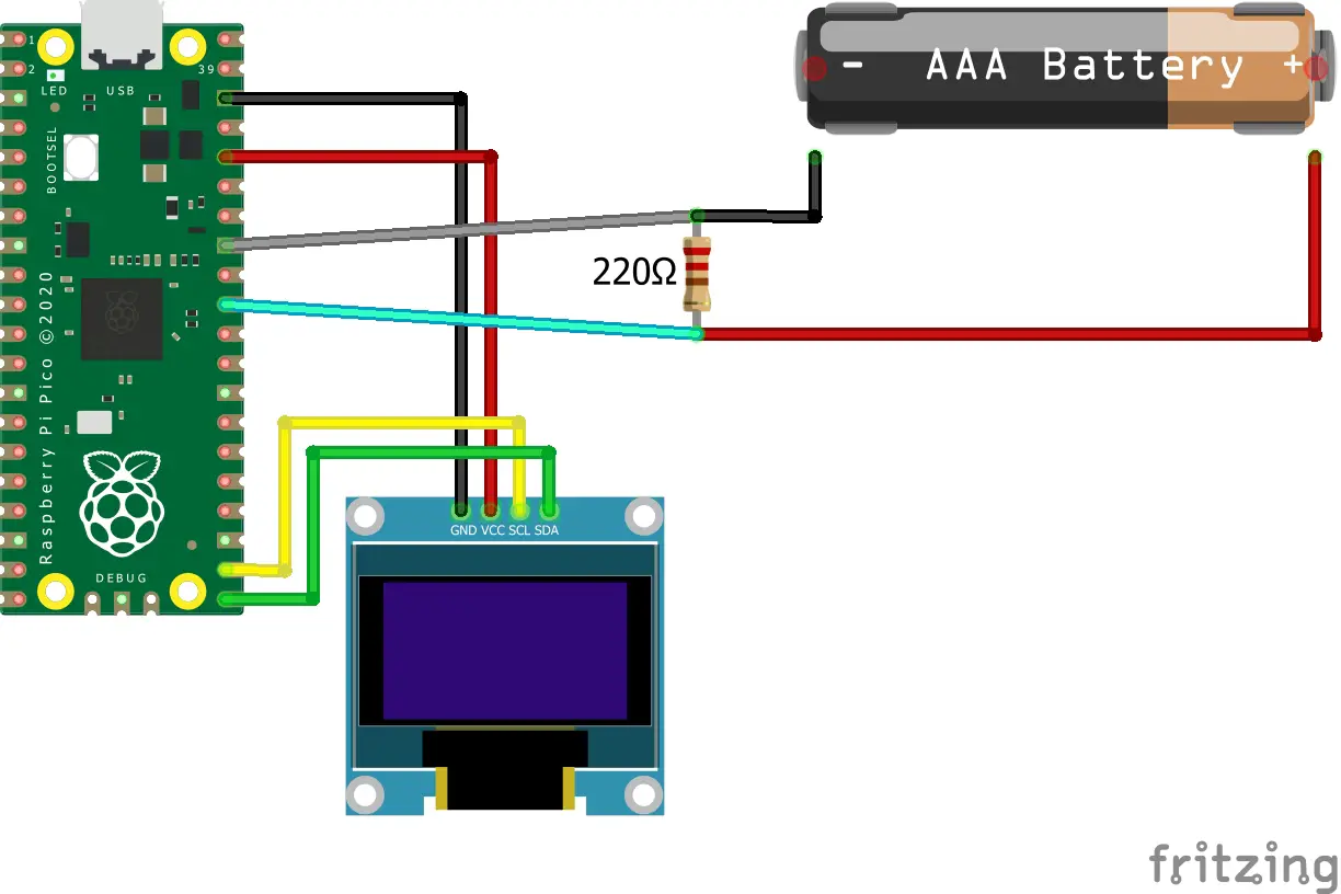
The following table will help with wiring:
| RPI Pico GP | RPI Pico function | External PIN |
| 38 | GND | SSD1306 OLED GND |
| 36 | 3V3(OUT) | SSD1306 OLED VCC |
| 33 | AGND (ground reference for analog pins) | pull-down resistor / battery negative pole |
| 31 | ADC0 | pull-down resistor / battery positive pole |
| 22 | I2C0 SCL | SSD1306 OLED SCL |
| 21 | I2C0 SDA | SSD1306 OLED SDA |
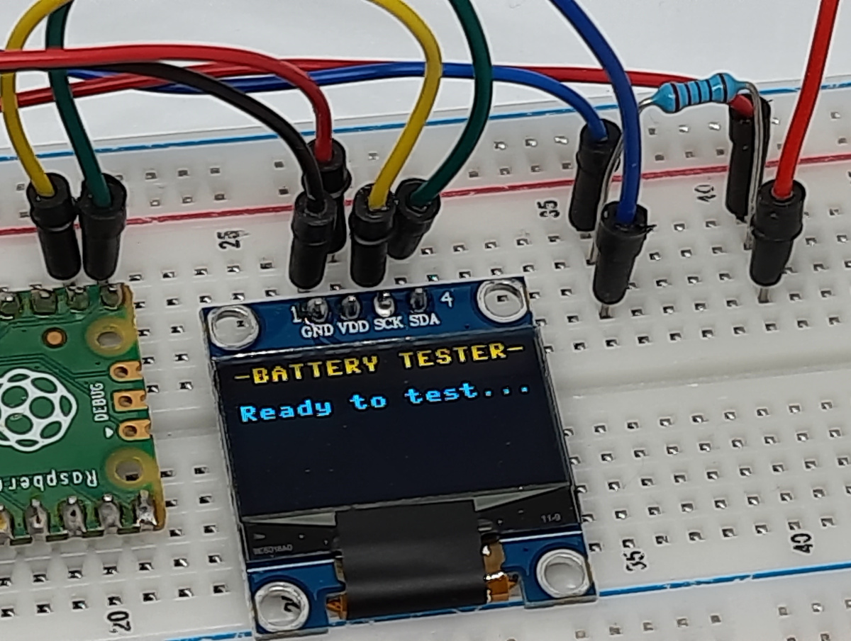
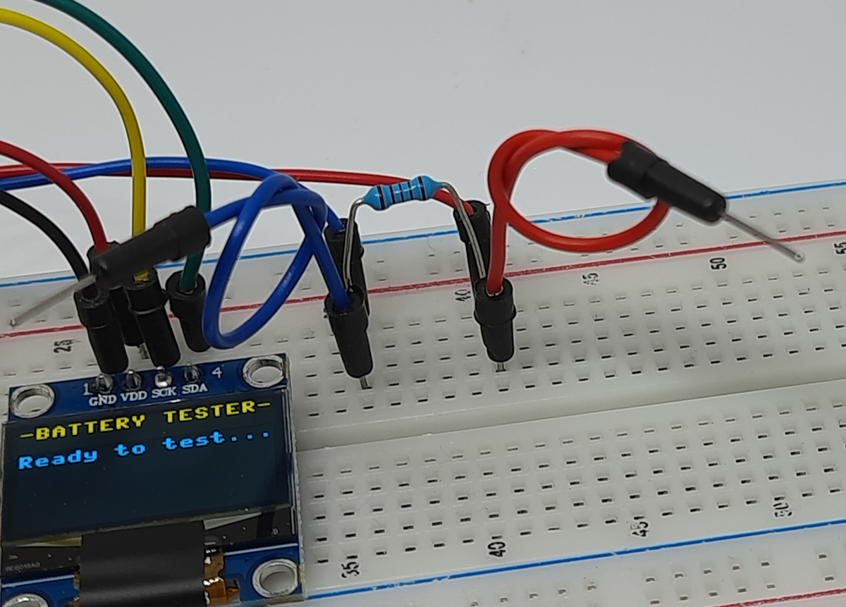
Please note that the wiring includes a 220 Ohm resistor. It’s a pull-down resistor and is used to avoid that the Raspberry PI Pico reads unstable values when nothing is connected. This is common with all the Raspberry PI boards. This resistor will keep the reading low when nothing is connected, not affecting the battery voltage reading.
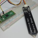
Please find below some pictures from my lab.
Get OLED Library and Raspberry PI Pico Battery Checker code
Connect RPI Pico to Thonny (you can refer to my tutorial about First steps with Raspberry PI Pico).
Please download and add the SSD1306.py library in your Raspberry PI Pico root folder, according to Adding external modules to MicroPython with Raspberry PI Pico tutorial. You can get it from my download area with the following link:
Moreover, please download my battery-check.py script on your computer and open it with Thonny.
Please remember that when you’ll need to run the battery checker program without a computer plugged into RPI Pico, you will need to rename the “battery-check.py” file to “main.py” in your Raspberry PI Pico storage.
The following paragraphs will describe my code line by line. A more detailed explanation of the SSD1306 OLED display is already available in my Add an OLED display to Raspberry PI Pico with MicroPython.
battery-check.py code
In the beginning, we’ll import the required modules:
from machine import Pin, I2C, ADC
from utime import sleep
import ssd1306
Then we initialize the SSD1306 OLED display module:
i2c = I2C(0, sda=Pin(16), scl=Pin(17))
display = ssd1306.SSD1306_I2C(128, 64, i2c)
The following line initializes the PIN to analog and sets the PIN number. If you are using a different analog PIN from your Raspberry PI Pico, please change the related number here:
Vin=ADC(26)
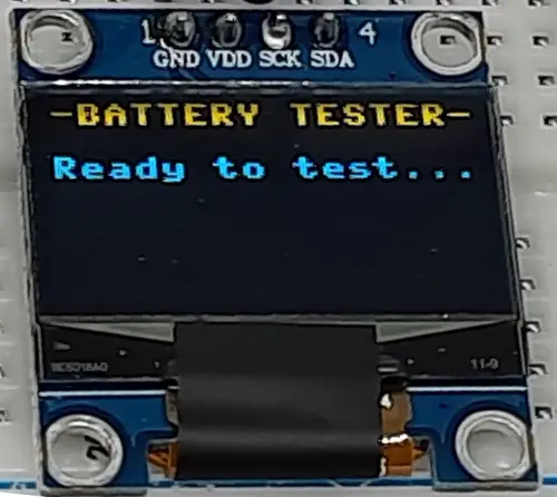
Then, a first custom function named open_circ() will handle the moments when no batteries are detected, which means that the circuit is open. This function simply shows a banner in your SSD1306 OLED display that will show the user that the device is ready to test a battery:
def open_circ():
display.text('-BATTERY TESTER-', 0, 0)
display.text('Ready to test...', 0, 16)
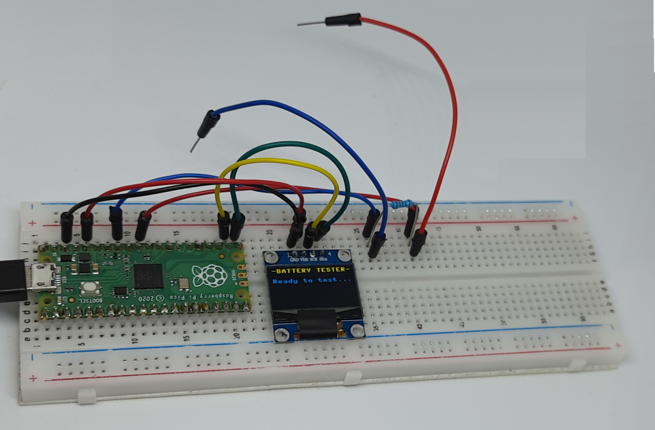
display.show()This will result as the following:
The second custom function handles when a battery is detected.
After managing the first two display lines, it reads the analog input value. It calculates the read voltage as the maximum voltage (3.3 V without a voltage divider), scaled according to a comparison between the read analog value and the maximum value on a 16-bit scale. It is important to note that Raspberry PI Pico reads the analog values within a 12-bit scale, but the MicroPython can read this with the ead_u16(), which scales the value into a 16-bit range.
Moreover, we round the “read_voltage” in order to show only 2 numbers after the comma.
At the end of this function, we print on the SSD1306 OLED display the resulting value:
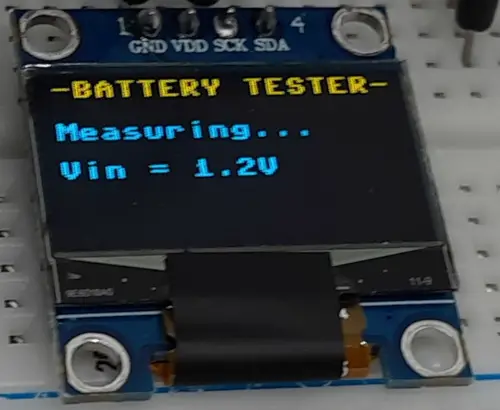
def measuring(adc_16_read):
    display.text('-BATTERY TESTER-', 0, 0)
    display.text('Measuring...', 0, 16)
    read_voltage=3.3*adc_16_read/65535
    read_voltage=round(read_voltage,2)
    display.text('Vin = '+str(read_voltage)+'V', 0, 32)
    display.show()
The following picture shows this function while running:
Then, the main program comes.
It starts by defining a “noise” variable. I’ve experienced that even with nothing attached and the pull-down resistor a small value comes from the Raspberry PI Pico analog PIN. With a 200 Ohm pull-down resistor, it has shown to me an average of 300 (in a 16-bit scale), which means an equivalent of 0,015V. To avoid these false readings, I’ve set a threshold (named “noise”) that will manage readings under this value as an open circuit. I’ve set this threshold to 2000 to let more room for higher pull-down resistors, as even a 2000 threshold will mean not reading voltage values under 0,1V:
noise = 2000The while True loop will run uninterruptedly the main program. A try statement will check if any errors occur. At each run the programs get the read value:
while True:
    try:
        reading = Vin.read_u16()
Here there is a commented print statement. If you want to check from terminal results (maybe for debugging or for tuning), you can uncomment this line:
#print(str(reading))The following fill property for the display will erase the whole SSD1306 OLED display at each run. This is required because otherwise, all the changes on display will overlap with the previous one. The customs function will work to keep the display showing the right lines:
display.fill(0)The following IF .. ELSE statement will use the proper custom function in the 2 possible cases. If there is no battery detected (that means the read value is lower than the defined noise threshold), the open_circ() function is executed. Otherwise, we’ll run the measuring() function, passing the 16-bit read value:
        if reading < noise:
            open_circ()
        else:
            measuring(reading)
A sleep statement will make the runs last at least 1 second so that the user will have enough time to read a stable value instead of a number changing too rapidly:
sleep(1)Finally, in case of any error, the except statement will perform a machine reset, that will reboot your Raspberry PI Pico:
    except OSError as e:
        machine.reset()
Run the Raspberry PI Pico Battery Checker
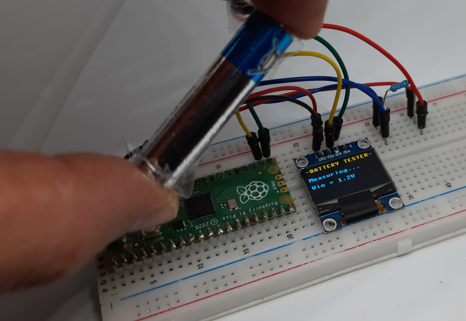
Finally, you can run the script. From Thonny, you can execute it by pressing the F5 key. If you have renamed the script to “man.py”, you can get results even by attaching a power supply to your Raspberry PI Pico, without the need for a connected PC. Once you will attach a battery with the wirings, you will see the voltage value on the OLED display, as shown in the following picture (I had to use scotch tape as the wirings were too small compared to my fingers while taking the picture 🙂 ).
Please, remember to connect the battery with the correct poles: the battery negative side has to stay with the AGND, while the positive side will interface with the A0 (GP26):
What’s Next
Interested to do more with your Raspberry PI Pico? Try to look at my Raspberry PI Pico tutorials for useful and funny projects!
Enjoy!

Open source and Raspberry PI lover, writes tutorials for beginners since 2019. He's an ICT expert, with a strong experience in supporting medium to big companies and public administrations to manage their ICT infrastructures. He's supporting the Italian public administration in digital transformation projects.
![]()
![]()
![]()
![]()
![]()
![]()
![]()