
Last Updated on 12th June 2024 by peppe8o
In this tutorial, I’m going to show you how this dual H-bridge motor driver integrated circuit works and how to setup an L293D with Raspberry PI Pico using MicroPython.
DC Motors are the most common and used components in robotics. With the L293D chip, you can drive many of these motors from Raspberry PI Pico with MicroPyton
The L293D H-bridge motor driver
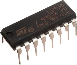
L293D is a chip integrated with a 4-channel motor drive. This is really versatile when using DC motors as it can drive up to 4 unidirectional motors or 2 bidirectional motors (also a mix is possible, even if rare). This chip provides bidirectional drive currents of up to 600 mA. It includes 2 power reference inputs: one gives power to motors (which can range between 4,5 V and 36 V), and the second powers the chip’s internal logic (which works at 5V).
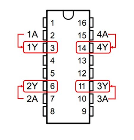
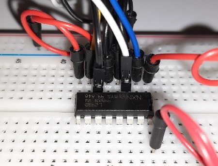
L293D has a 16 PIN layout:
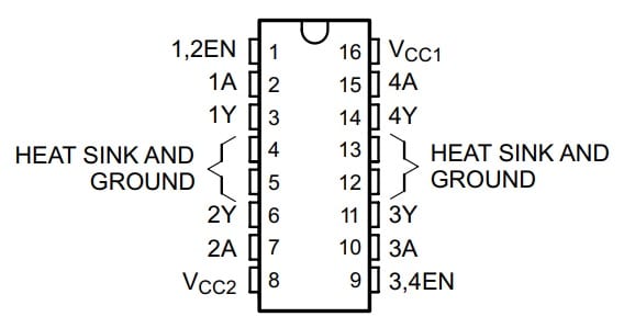
As you can see, PIN names already identify 4 main channels: 1A/1Y, 2A/2Y, 3A/3Y and 4A/4Y. Pin functions are the following:
- “1,2EN” – physical No 1 – enables output to channels 1 and 2
- “(1..4)A” – physical No 2, 7, 10, 15 – they are the driver inputs. Each one enables its related driver output
- “(1..4)Y” – physical No 3, 6, 11, 14 – they are the drive outputs. These PINs are to be connected directly to DC motors
- “3,4EN” – physical No 9 – enables output to channels 3 and 4
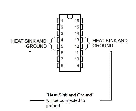
- GROUND – physical No 4, 5, 12, 13 – Device ground and heat sink pin. These PINs are to be connected to a common ground
- Vcc1 – physical No 16 – 5V supply for internal chip logic
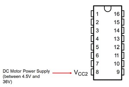
- Vcc2 – physical No 8 – Vcc power supply which will be transferred to motors (from 4.5V to 36V)
How L293D Works
To better understand how this chip works, let’s have a closer look at its internal logic:
Looking at L293D PIN layout, its usage will be as follows.
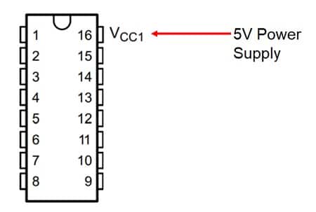
Vcc1 power the chip logic (working at 5V). This PIN simply needs a 5V power to get L293D powered on:
Vcc2 connects to the power supply too, but this PIN gives power to DC motors. You can use it with a voltage level between 4.5V and 36V without affecting L293D chip logic, as motor-enabling PINs are internally decoupled from power lines:
Heat sink and ground PINs go to the ground:
Each ENable port works with a specific chip side.
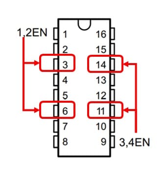
The following logic schema explains better the Enable function:
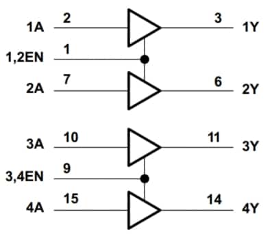
As you can see from the above picture, each “EN” PIN enables one side chip. Even if it can appear as a chip limitation, it turns into a great function as you can trigger this PIN with a PWM signal which, using the motor inertia, will reduce or increase the DC motor rotations. Similarly to Raspberry PI PWM with LED, for example, a Duty Cycle of 50% will result approximatively in a speed reduction to 50%.
Finally, each “A” PIN directly controls its closest output port:
Even if you can drive 4 motors (each one having one pole connected to the ground and the other one to a “Y” port), common usage connects the 2 poles of a single DC motor to 1Y and 2Y (or 3Y and 4Y). In this way, you can control motor rotation direction. For example, using 1Y and 2Y poles, you can set 1A to logic 1 (high) and 2A to logic 0 (low) getting a specific direction. Setting 1A to logic 0 (low) and 2A to logic 1 (high) you will get the opposite direction.
As DC motors use a lot of power, you will probably need an external power supply to make them rotate with enough speed. For this reason, you may also need an
What We Need
As usual, I suggest adding from now to your favourite e-commerce shopping cart all the needed hardware, so that at the end you will be able to evaluate overall costs and decide if to continue with the project or remove them from the shopping cart. So, hardware will be only:
- A common computer (maybe with Windows, Linux or Mac). It can also be a Raspberry PI Computer board
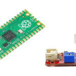
- Raspberry PI Pico microcontroller (with a common micro USB cable)
- L293D chip
- DC motor
- breadboard
- breadboard power supply module
- dupont wirings
Check hardware prices with the following links:


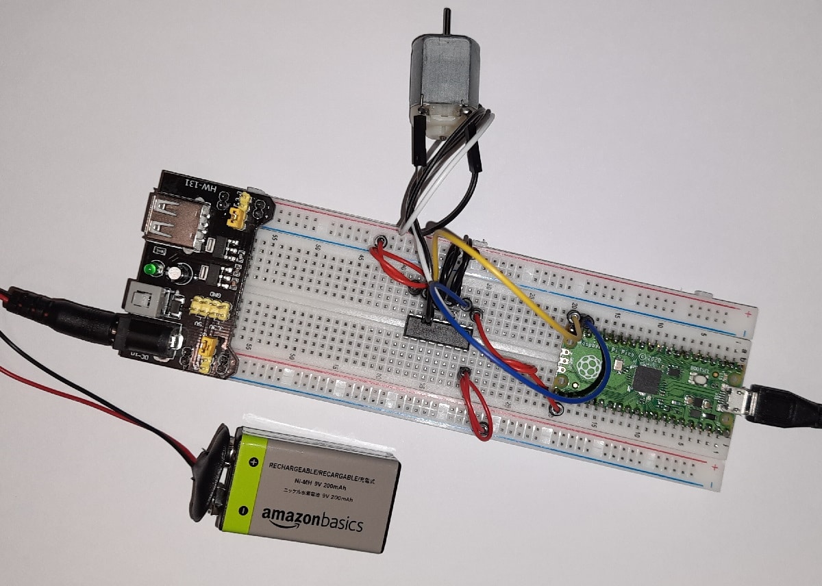
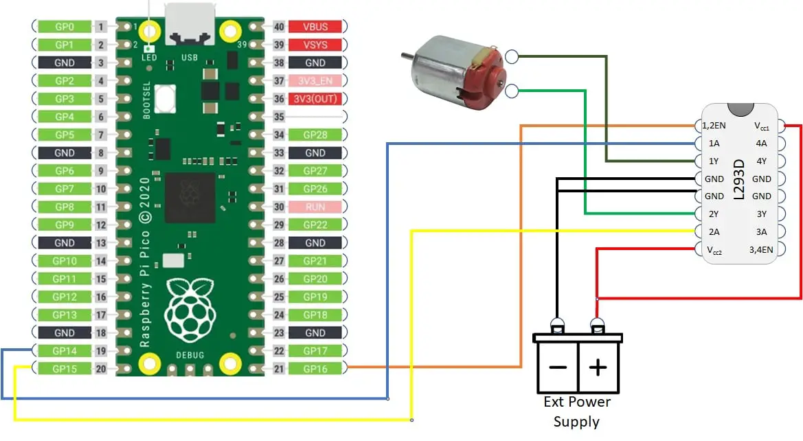
Wiring Diagram
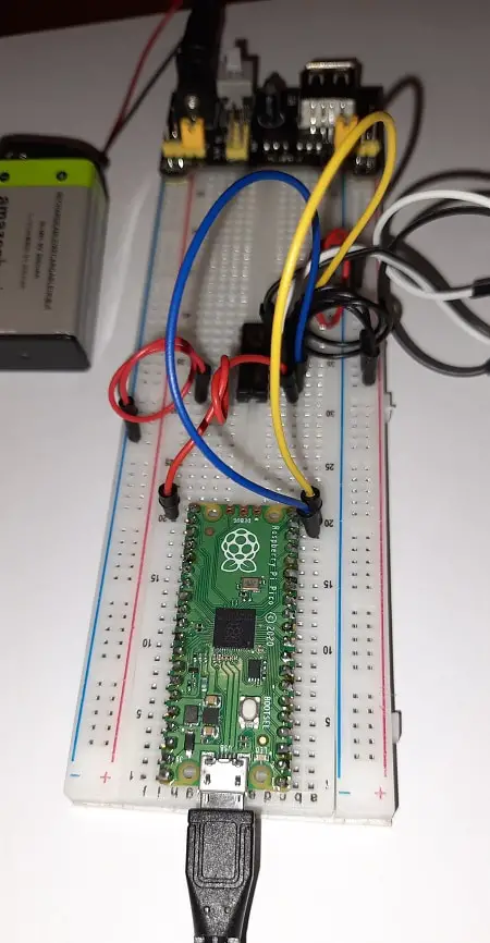
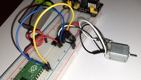
Please find in the following picture the wiring used in my project:
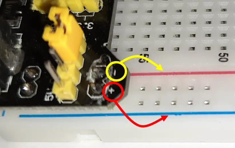
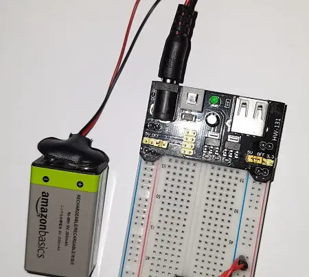
When using breadboard power modules, please check if the module poles and breadboard rails colours are matching. In my case, I have been struggling for a while because the breadboard red line (usually indicating a positive pole) corresponds to the negative of my power module (see picture below). Anyhow, power module ones are overcome.
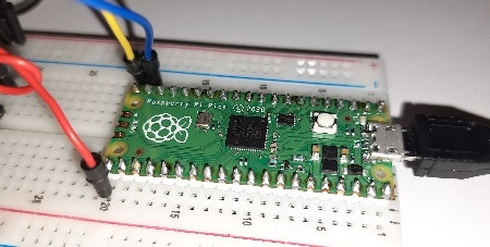
Please find below some additional pictures from my setup:
When running the very first tests, keep checking the L293D temperature. If it doesn’t work and the chip becomes hot, you will probably have a wiring error.
Step-by-Step Procedure
Prepare cabling according to previous paragraph. Connect RPI Pico to Thonny (you can refer to my tutorial about First steps with Raspberry PI Pico). Download my picoL293D.py script on your computer and open it with Thonny.
The following paragraphs will describe my code line by line.
First 2 lines import the required modules:
from machine import Pin, PWM
from time import sleep
We use variables associated with Raspberry PI Pico PINs numbers to get better code management and readability:
pwmPIN=16
cwPin=14
acwPin=15
A function is used to call DC motor action.
def motorMove(speed,direction,speedGP,cwGP,acwGP):As you can see, this function requires 5 parameters
- speed [between 0 and 100] – specifies how fast the motor will rotate in percentage. It is used with PWM duty cycle to reduce or increment power arriving at DC motor
- direction [integer number] – specifies rotation side. Positive values will result in clockwise (CW) rotation. Negative values will result in ant-clockwise (ACW) rotation. 0 (zero) will result in the motor being put off
- speedGP [integer number] – passes the PWM pin number
- cwGP and acwGP [integer numbers] – pass the L293D single ports number
Consider that if you will get the opposite rotation, you will need to invert DC motor ports connection to L293D or exchange values between acwPin and cwPin parameters.
The following 2 lines manage wrong speed values, keeping them in the 0-100 range:
  if speed > 100: speed=100
  if speed < 0: speed=0
A Speed (with upper “S”) object variable will manage the PWM PIN. We’ll set it accordingly, with a frequency of 50Hz:
  Speed = PWM(Pin(speedGP))
  Speed.freq(50)
Same way, we’ll initialize cw (clockwise) and acw (anti-clockwise) PIN objects. They will be digital outputs (no need for analog outputs):
  cw = Pin(cwGP, Pin.OUT)
  acw = Pin(acwGP, Pin.OUT)
DC motor speed is finally set using the duty cycle. Considering that the duty cycle uses a 16-bit function (duty_u16), it will range between 0 and 65,536. Speed will be set accordingly and using function input from the user as a percentage of the range:
Speed.duty_u16(int(speed/100*65536))Following if statements will control the side of DC motor rotation. Negative values will enable acw pin, disabling cw one and resulting in anti-clockwise rotation:
  if direction < 0:
      cw.value(0)
      acw.value(1)
0 (zero) will disable both pins, resulting in the motor powered off (regardless of speed values):
  if direction == 0:
      cw.value(0)
      acw.value(0)
Positive values will enable cw pin, disabling acw one and resulting in clockwise rotation:
  if direction > 0:
      cw.value(1)
      acw.value(0)
Here ends the motorMove function. The last lines give a simple usage example, getting a full-speed, anti-clockwise rotation for 5 seconds:
motorMove(100,-1,pwmPIN,cwPin,acwPin)
sleep(5)
And finally powering off the motor:
motorMove(100,0,pwmPIN,cwPin,acwPin)Running the picoL293D Script
Run this script in your Thonny IDE (F5) and you will start seeing your DC motor moving for 5 seconds according to the set side and speed, then stopping.
What’s Next
Interested to do more with your Raspberry PI Pico? Try to look at my Raspberry PI Pico tutorials for useful and funny projects!
Enjoy!

Open source and Raspberry PI lover, writes tutorials for beginners since 2019. He's an ICT expert, with a strong experience in supporting medium to big companies and public administrations to manage their ICT infrastructures. He's supporting the Italian public administration in digital transformation projects.
![]()
![]()
![]()
![]()
![]()
![]()
![]()

The Pico has a 5v power pin. Could you power the L 293D from that?
DC motors drain a lot of current, a bit too much for the power chain inside our Raspberry PI Pico microcontroller. For ashort test is ok, but for long usage I suggest using a different power souce