Some links in this post may be affiliate links. We may get paid if you buy something or take an action after clicking one of these, but without addictional costs for you compared to direct buying.
Last Updated on 20th October 2023 by peppe8o
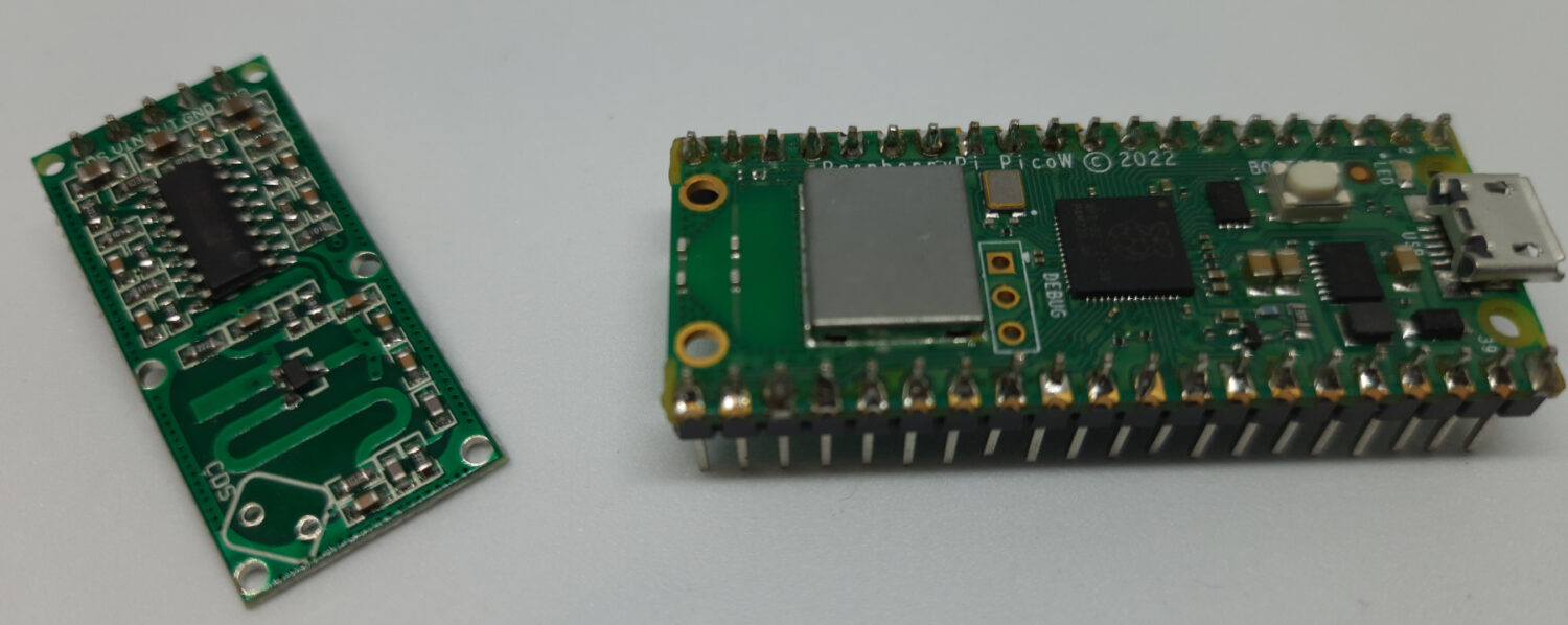
This tutorial will show you how to use a RCWL-0516 with Raspberry PI Pico, by using MicroPython. I will also include the wiring diagram to show how to interface the module with your microcontroller.
What is the RCWL-0516 Radar Sensor
The RCWL-0516 is a great device working on an interesting principle: the Doppler effect. It can detect object motion by calculating the Doppler effect from objects by emitting microwave signals and reading the returning signals. But the RCWL-0516 sensor makes the usage of results for motion detection far simpler because you don’t have to make any calculation as it will directly output to you a high-level output (if a motion has been detected) or a low-level output (if no motion has been detected).
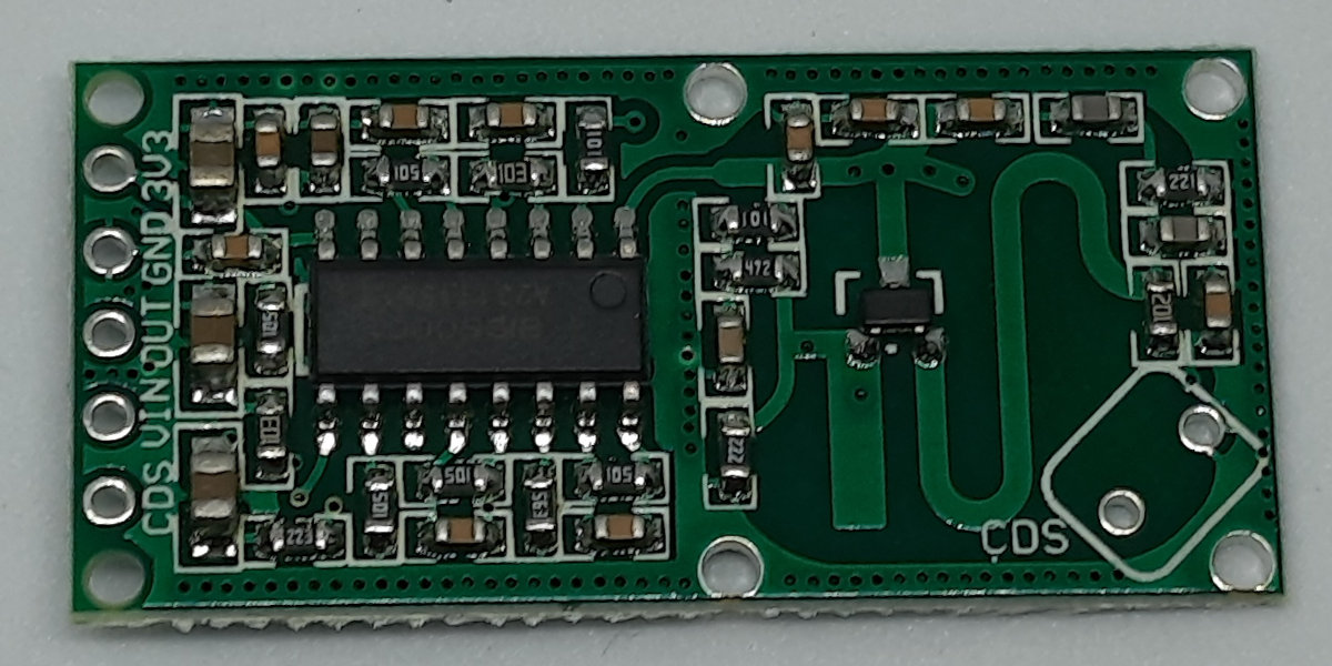
It checks for new motion signals every 2 seconds and is capable of covering a range of 7 meters.
It is important to note that the RCWL-0516 can’t give you any info about the distance or the speed of the moving object, so it will provide you with just a motion/NO motion result.
The RCWL-0516 has an internal RCWL-9196 chip which makes the hard part of the job. This chip transmits microwaves approximatively at 3.2 GHz and calculates the received microwaves. If the returning microwaves have the same frequency as the transmitted ones, there has been NO motion.
If the module receives waves at different frequencies, at least one object has moved, creating the Doppler effect.
In this way, the module is able to define if there is a motion in its operating range by evaluating it from the Doppler effect analysis.
Because of the usage of microwaves, the RCWL-0516 is able to detect motion even behind a thin wall or any low microwave-reflection materials. But, on the other hand, it suffers if installed near WiFi devices. For this reason, you will have to test even if the Raspberry PI Pico internal WiFi may affect your results.
RCWL-0516 PINOUT
The module has 5 main unpopulated PINs:
| PIN Label | Description |
|---|---|
| 3V3 | Regulated 3.3V Output (max 100mA) |
| GND | Ground reference Input for module |
| OUT | The Output from the sensor |
| VIN | The voltage Input for the module |
| CDS | Sensor Disable |
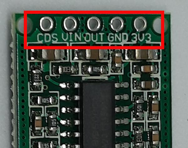
While quite all of them appear intuitive (please note that the 3V3 is an OUTPUT), the CDS PIN allows you to force the module disabling, so that your program can detect motion only at specified conditions/times.
The module also includes two unpopulated PINs labelled as CDS. These PINs allow you to solder a photoresistor in order to disable the module during the daylight.
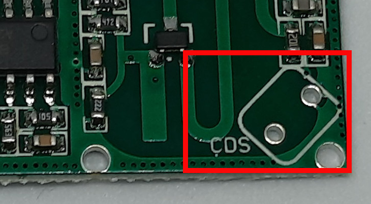
In the RCWL-0516 backend, you can also find 3 more points to hack the module:
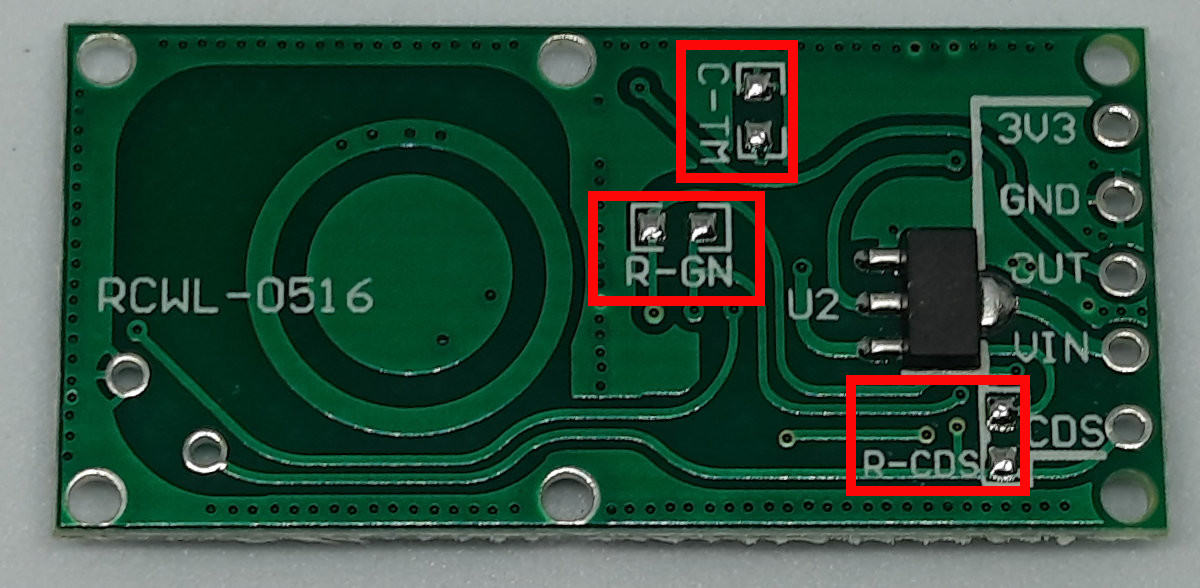
The C-TM controls the trigger time. You can extend this default time by adding an SMD capacitor, but there’s very poor documentation on how to make this change.
The R-GN allows you to reduce the detection range from the default 7 meters by soldering a resistor. Many web pages about this say that you can add a 1M Ohm resistor to reduce the range to 5 meters, but the web lacks of more info about dimensioning the resistor for customized results.
Finally, the R-CDS allows you to add a resistor in parallel with the CDS, in order to customize the light level which enables/disables the module
RCWL-0516 Additional Resources
A good reference for the RCWL-0516 module can be found at https://github.com/jdesbonnet/RCWL-0516.
The RCWL-0516 specs are shown in the next table:
| Property | Value |
|---|---|
| Dimensions | 36 x 18 mm |
| Operating Voltage | 4-28V |
| Operating Current | 2.8mA (typical); 3mA (max) |
| Detection Distance | 5-9m |
| Transmitting Power | 20mW (typical); 30mW (max) |
| Output Voltage | 3.2-3.4V |
| Output Control Low Level | 0V |
| Output Control High-Level | 3.3V |
| Operating Temperature | -20~80 Celsius |
| Storage Temperature | -40~100 Celsius |
What We Need
As usual, I suggest adding from now to your favourite e-commerce shopping cart all the needed hardware, so that at the end you will be able to evaluate overall costs and decide if to continue with the project or remove them from the shopping cart. So, hardware will be only:
- A common computer (maybe with Windows, Linux or Mac). It can also be a Raspberry PI Computer board
- Raspberry PI Pico microcontroller (with a common micro USB cable)
- RCWL-0516 module
- breadboard (optional)
- dupont wirings
Step-by-Step Procedure
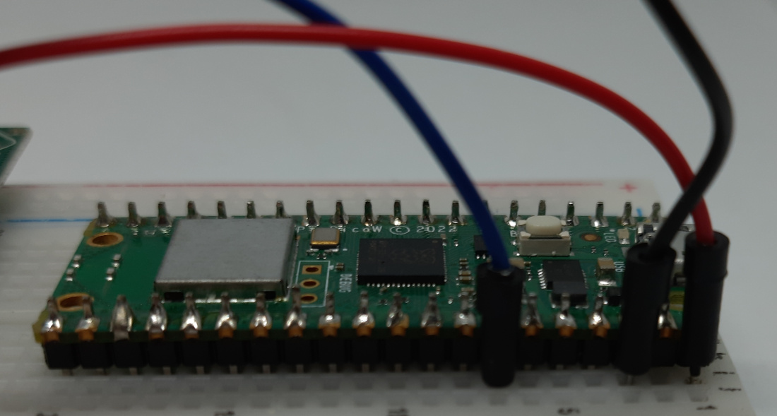
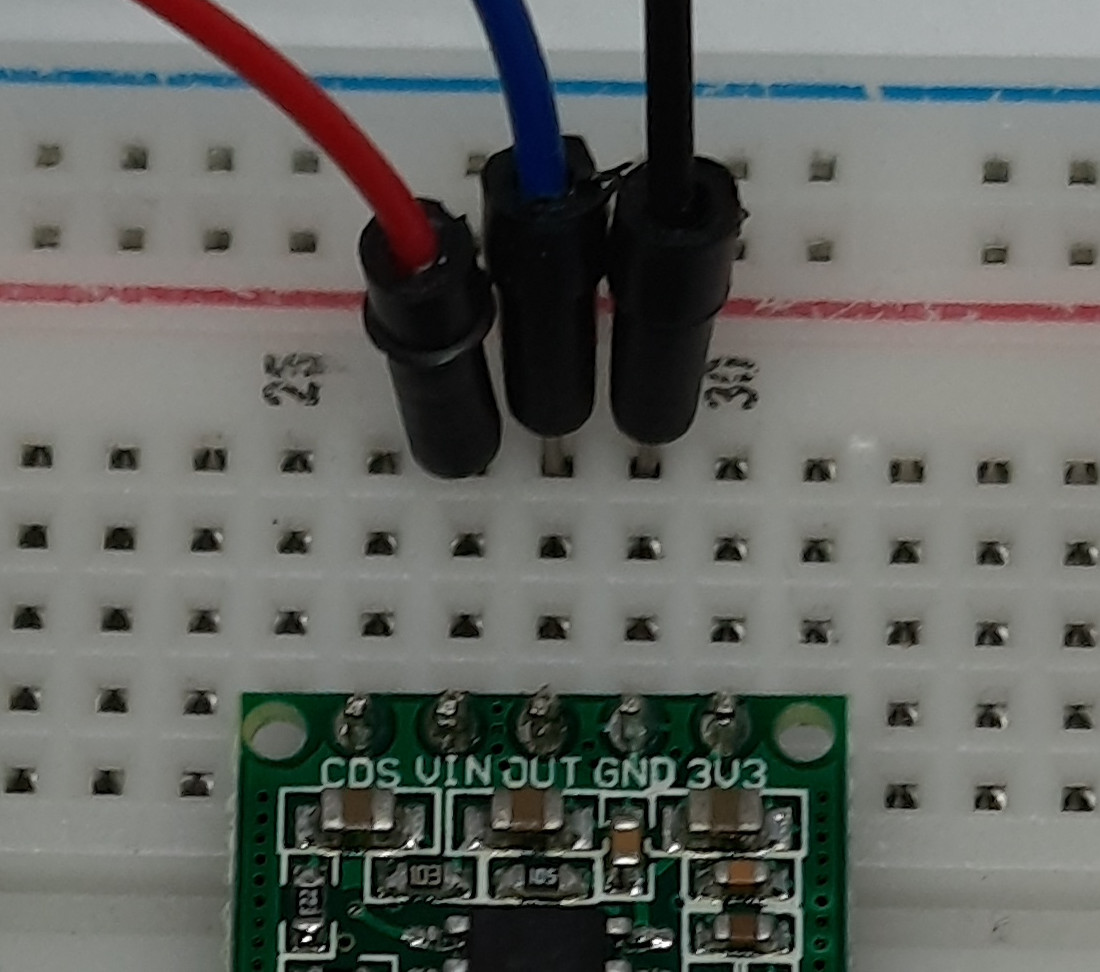
RCWL-0516 and Raspberry PI Pico Wiring Diagram
Please arrange the wiring as follows, according to the Raspberry PI Pico Pinout:
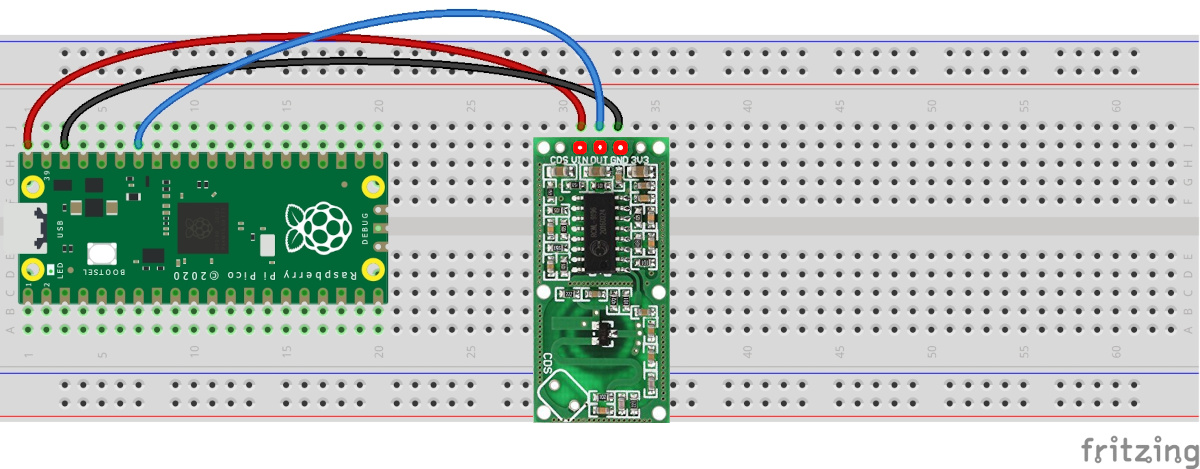
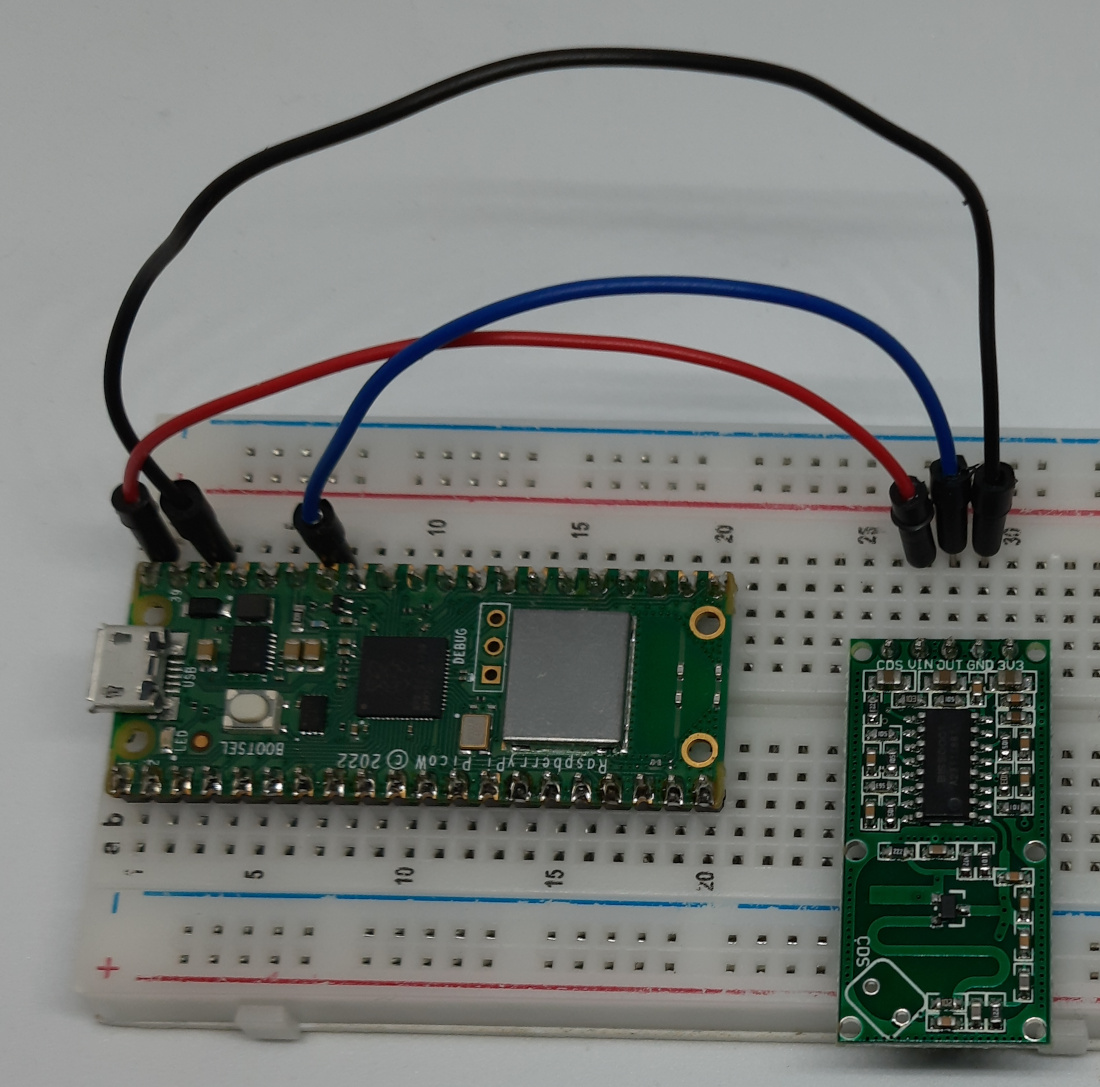
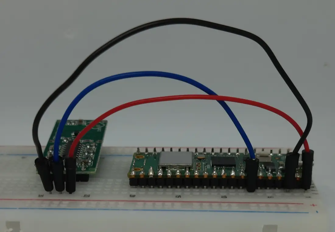
Please find below some pictures from my home lab, even if the wiring is really simple:
First Step: Install MicroPython on Raspberry PI Pico
Connect your Raspberry PI Pico to Thonny and install MicroPython. For the very first steps and to install MicroPython, you can refer to my tutorial about the First steps with Raspberry PI Pico.
Download the Code for RCWL-0516 and Raspberry PI Pico
Get my MicroPython script for RCWL-0516 with Raspberry PI Pico from the following link:
You can execute it from Thonny with your microcontroller connected. The following lines will explain the code line by line, while the following chapter will show you the expected results.
The code starts by importing the required modules. The sleep() function is not strictly necessary, but it reduces the number of checks for the radar sensor output by adding a small “sleep” time at each loop.
from machine import Pin
from time import sleep
For code clarity, I associated 2 variables to the input port number from the Raspberry PI Pico side (connected to the RCWL-0516 output and the related MicroPython PIN object:
RcwlOut=28
motionDetected = Pin(RcwlOut,Pin.IN)
Then, another code clarity practice: the module can give only 2 possible states, motion detected and motion NOT detected. I use 2 custom functions where you can add your custom tasks to run on both cases. For this example, both functions will just print the motion detection status. The “end” option will make the result appearing always on the same Thonny shell line, instead of infinitely scrolling down, as explained in my Raspberry PI Pico Print() Advanced Options tutorial:
def motionDetTasks():
    print("MOTION DETECTED!   ",end="\r")

def noMotionDetTasks():
    print("No motion detected!",end="\r")
In this way, the main loop will just check if the radar sensor output raises to “1” (for motion detection) or goes to “0” (for no motion detection), so calling the proper tasks with the custom functions previously defined. The sleep line will make the code execution a bit slower to make you clearly see the value changes:
while True:
    if motionDetected.value():
        motionDetTasks()
    else:
        noMotionDetTasks()
    sleep(0.1)
Running the pico-rcwl-0516.py Script
Run this script in your Thonny IDE (F5) and you will start reading the output from the radar sensor. At the beginning, if nothing moves in front of the sensor you will read the related message:
>>> %Run -c $EDITOR_CONTENT
No motion detected!
In order to force motion detection, you can move your hand upon the RCWL-0516 module, so that your shell will show the new state:
>>> %Run -c $EDITOR_CONTENT
MOTION DETECTED!
What’s Next
Interested in doing more with your Raspberry PI Pico? Try to look at my Raspberry PI Pico tutorials for useful and funny projects!
Enjoy!
Open source and Raspberry PI lover, writes tutorials for beginners since 2019. He's an ICT expert, with a strong experience in supporting medium to big companies and public administrations to manage their ICT infrastructures. He's supporting the Italian public administration in digital transformation projects.

