
Last Updated on 31st March 2023 by peppe8o
In this tutorial, we will use a tilt sensor with the Arduino Uno to measure an object’s orientation or tilt. This sensor has wide applications in toys, game controllers, alarm systems, and robots. It works based on the alternative to the switch as it works on 1 and 0 logics.
Tilt Sensor Description
A tilt sensor’s basic operation is based on two conducting pads or switches and two conductive metal balls that are put inside a tiny container or enclosure. It includes a little arm or lever that revolves around the enclosure. When the enclosure tilts or rotates, the metal balls inside it move, and this change in position creates a change in the electrical contact between the two conducting pads.
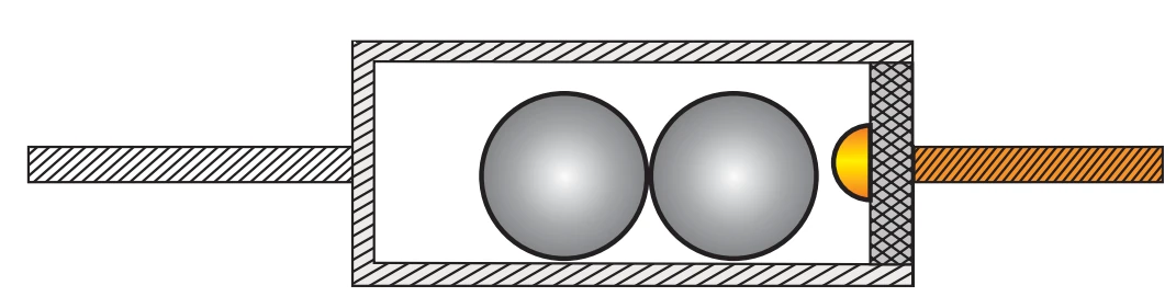
The tilt sensor works by detecting the movement of the conductive metal balls inside it. And this movement causes a change in the electrical contact between the two conductive pads, which detects by the circuitry connected to the sensor.
Working principle of Tilt Sensor
The circuitry connected to the tilt sensor usually consists of an amplifier circuit and a comparator circuit. The amplifier circuit amplifies the small electrical signal produced by the tilt sensor and the comparator circuit compares this amplified signal to a reference voltage. If the amplified signal is higher than the reference voltage, it means that the tilt sensor tilt in one direction. And if it is lower than the reference voltage, it means that the tilt sensor tilt in the opposite direction.
For this tutorial, I will use a buzzer in order to generate an acoustic signal when the tilt sensor checks a tilting.
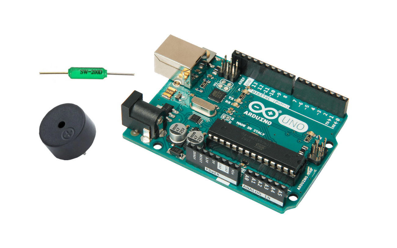
What We Need

As usual, I suggest adding from now to your favourite e-commerce shopping cart all the needed hardware, so that in the end you will be able to evaluate overall costs and decide if continue with the project or remove them from the shopping cart. So, hardware will be only:
Step-by-Step Procedure
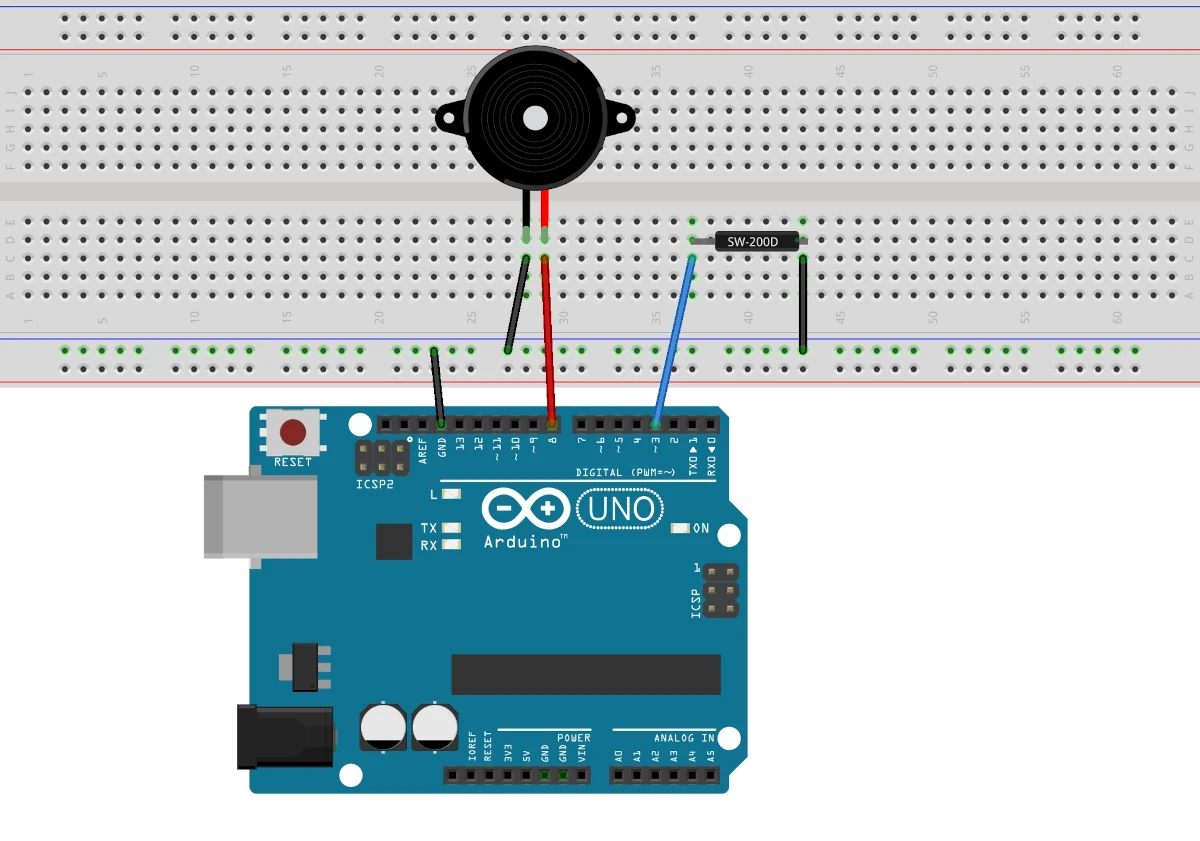
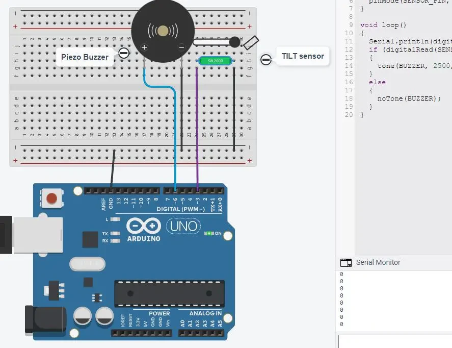
Wiring Diagram of Tilt Sensor with Arduino Uno
It is important to note that, when using switch devices or sensors connected to two Arduino PINs, it’s always safer to use the ground PIN and a software “pulled-up” reading PIN. The pull-up will keep the PIN reading at a HIGH (1) level when it isn’t connected to any source, while it goes safely to LOW (0) when connected to the ground. This allows us to avoid using an external resistor and also avoid overvoltage for very short high current peaks at the switch closing. This means that our code will work in an inverse logic (1 -> open circuit, 0 -> closed circuit).
The tilt sensor has two pins. One of these can be connected to any digital pin. For this tutorial I will connect to the Pin 3 of Arduino Uno, please correct the code if you’re going to use a different one.
The other side of the tilt sensor connects to the ground.
| Arduino | Tilt Sensor | Buzzer |
|---|---|---|
| GPIO 3 | Pin 1 | |
| GND | Pin 2 | |
| GPIO 6 | Pin + | |
| GND | Pin – |
Please find below a picture showing the Tilt Sensor and Arduino Uno wiring diagram:
Get the code for the Tilt Sensor with Arduino
Connect your PC to Arduino and open Arduino IDE. For the very first steps, you can refer to Connecting Windows PC with Arduino tutorial. You can get the .ino code from my download area with the following link:
Code Explanation
Section 1: Setup and before setup
In this section, we define the digital PIN for the sensor (3) and the PWM PIN for the buzzer (6). The buzzer works on the PWM so it’s important that it should be connected to the PWM pin. On the Arduino board, the pin with the (~) sign is the PWM.
#define SENSOR_PIN 3
#define BUZZER 6
In the setup, we set the baud rate of serial monitor to 9600. Then, we initialize the sensor pin as input with a pull-up to remain high if the sensor does not give the 0 logic.
void setup()
{
  Serial.begin(9600);
  pinMode(SENSOR_PIN, INPUT_PULLUP);
}
Section 2: Loop section
This is the section for the main loop. The digitalRead command measures our sensor value.
void loop()
{
  Serial.println(digitalRead(SENSOR_PIN));
If the tilt sensor is tilted, then it gives the 0 (zero) logic and the buzzer turns on.
  if (digitalRead(SENSOR_PIN) == LOW)
  {
    tone(BUZZER, 2500, 125); // tone(pin number , frequency, time)
  }
Otherwise, the buzzer stops and gives no sound.
  else
  {
    noTone(BUZZER);
  }
}
Tilt Sensor with Arduino Simulation
Please find below a demo simulation.
As in the picture, the serial monitor shows the output from the tilt sensor. When the tilt sensor is not tilted, it gives 1 logic, at which the buzzer is set to give no sound:
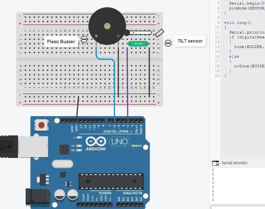
When the tilt sensor rotated, then it gives 0 logic to pin 3 of Arduino, at which the buzzer is set to turn on and gives sound.
What’s Next
Please find more tutorials on Arduino in peppe8o Arduino archives.
Enjoy!
Umar Jamil
For any queries and help with work, please contact me at:
Whatsapp: +92-346-661-7017/ Link
Email: umarjamil0007@gmail.com

I'm an Electronic Engineer, well-skilled to solve the issues of hardware and software. I do have laboratory which contains unlimited sensors and modules for testing the working. Also, I am experienced in Arduino programming, Android mobile application, microcontroller programming, IOTs and embedded projects. I provide services to control, realize the sensor data in the Mobile Application. For any queries and help for work Contact: Whatsapp:+92-346-661-7017 Email: umarjamil0007@gmail.com
![]()


