
Last Updated on 2nd September 2023 by peppe8o
In this tutorial, we will build our own calculator with Arduino, a 4×4 keypad and a 16×2 LCD display. The input will be given through the keypad (4×4 keypad) and the output will be displayed on the 16×2 LCD screen. This calculator will perform simple operations like Addition, Subtraction, Multiplication and Division with whole numbers.
One of the most basic but formative projects with Arduino Uno is performing algebraic calculus with a custom-designed calculator by using a 4×4 keypad, Arduino Uno and the 16×2 LCD display. The calculations include addition, subtraction, multiplication and division.
Calculator Description
A calculator is a machine which performs mathematical functions like addition, subtraction, multiplication, and division. Some also do square roots, and many other complex operations like a scientific calculator. Here we will design a simple calculator which will perform only addition, subtraction, multiplication, and division. Still, when you understand the basic principle then you can make your own scientific calculator using Arduino.
Working Phenomena
For making a calculator, we require 3 devices.
- Input device
- Processing device
- Output device
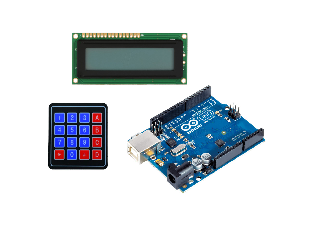
For Input we will use a 4×4 keypad, for performing the calculations we use Arduino Uno and for displaying the output we will use a 16×2 LCD.
What We Need

As usual, I suggest adding from now to your favourite e-commerce shopping cart all the needed hardware, so that in the end you will be able to evaluate overall costs and decide if continue with the project or remove them from the shopping cart. So, hardware will be only:
Check hardware prices with the following links:


Step-by-Step Procedure
The Calculator has three main components: Arduino Uno, a keypad and an LCD. First, we will discuss the 4×4 keypad it has 8 pins. 4 pins for rows and 4 pins for the columns. By combining these rows and columns, we get the number that the user has pressed. Secondly, the 16×2 LCD has 16 columns and 2 rows. we can display 32 characters on the 16×2 LCD. We can use this 16×2 LCD directly with the Arduino or we can use it with the I2C module. Here in this tutorial, we will use the LCD in both ways (directly and with the I2C module). And the Arduino will perform calculations on the given numbers.
First of all, the user will input the first operand (number) after this user will choose the operator (+,-,*,/) then the second operand (number) and after this user will press the “=” button for the output. In this calculator, the keypad has operators different from the mathematical operators(+,-,*,/) but the working is according to the mathematical operators. The keypad has the following operator representation.
A(+) is use for addition.
B(-) uses for subtraction.
C(*) uses multiplication.
D(/) uses for division.
#(=) uses for equal to (output).
*(.) uses for the decimal point.
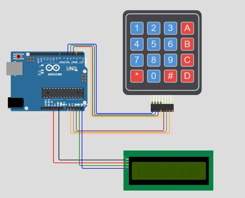
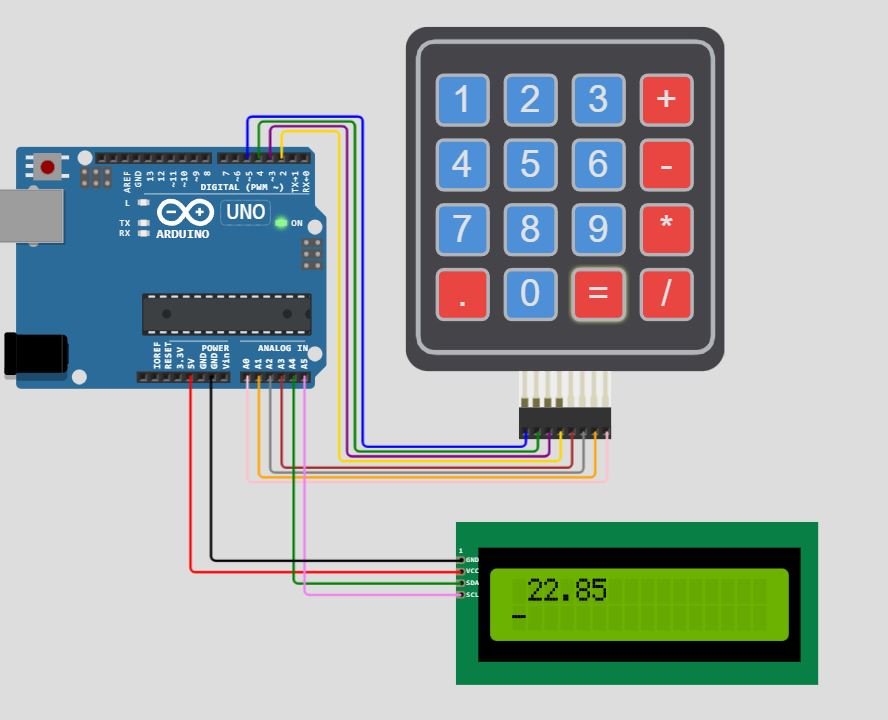
Wiring Diagram of calculator
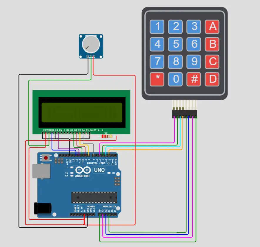
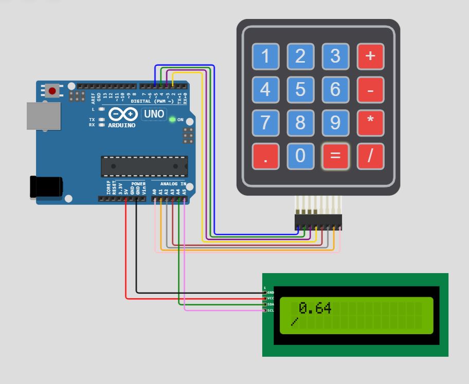
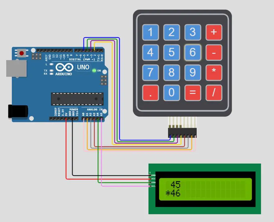
In the circuit diagram keypad row pins are connected to Arduino pins (2,3,4,5) and keypad column pins are connected to the Arduino pins (A0, A1, A2, A3). LCD(16×2) is directly connected to the Arduino pins (7,8,9,10,11,12). One potentiometer is connected with LCD (VEE/V0) pins to control the brightness of the LCD. For interfacing the LCD we can also use the I2C module in this way the need only two wires (A4, and A5) to communicate with the LCD. Both the wiring diagrams are given below.
Please follow the wiring from the following picture, according to Arduino Uno Pinout:
Get the code and Library for the Calculator
Connect your PC to Arduino and open Arduino IDE. For the very first steps, you can refer to Connecting Windows PC with Arduino tutorial. You can get the .ino code from my download area with the following link:
- i2c_based_calculator.ino (for I2C based LCD)
- 16X2lcd_based_calculator.ino
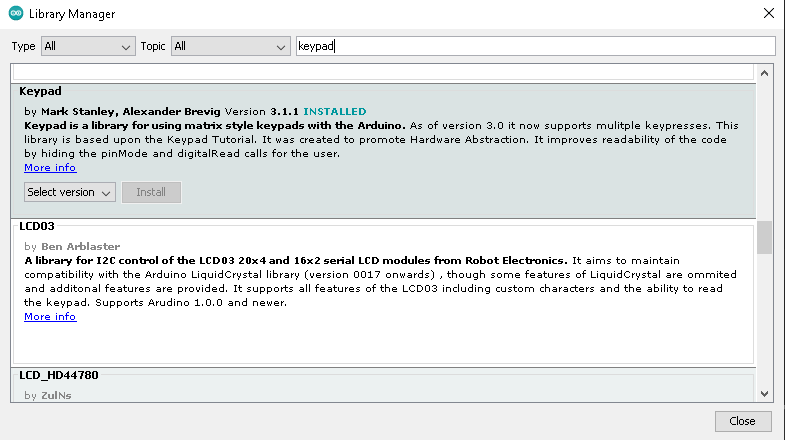
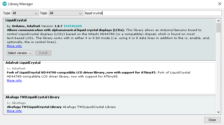
You also need to install the following libraries, according to my Install Arduino Libraries: methods to add libraries with Arduino IDE tutorial.
Code Explanation
In this code explanation section, I will explain the code refers to the LCD module without the I2C backpack, even if the 2 ino files are the same besides the “include” and the LiquidCrystal object initialization.
Section 1;
This is the section before setup which uses for globe variables defining and libraries additions.
LiquidCrystal.h is the library for 16×2 LCD.
keypad.h is the library for 4×4 keypads.
Here we have defined the instance LiquidCrystal lcd(12, 11, 10, 9, 8, 7) for the LCD. Keypad rowPins[KEYPAD_ROWS] = {5, 4, 3, 2} and keypad colPins[KEYPAD_COLS] = {A3, A2, A1, A0}.
#include <LiquidCrystal.h>
#include <Keypad.h>

/* Display */
LiquidCrystal lcd(12, 11, 10, 9, 8, 7);

/* Keypad setup */
const byte KEYPAD_ROWS = 4;
const byte KEYPAD_COLS = 4;
byte rowPins[KEYPAD_ROWS] = {5, 4, 3, 2};
byte colPins[KEYPAD_COLS] = {A3, A2, A1, A0};
char keys[KEYPAD_ROWS][KEYPAD_COLS] = {
  {'1', '2', '3', '+'},
  {'4', '5', '6', '-'},
  {'7', '8', '9', '*'},
  {'.', '0', '=', '/'}
};

Keypad keypad = Keypad(makeKeymap(keys), rowPins, colPins, KEYPAD_ROWS, KEYPAD_COLS);

uint64_t value = 0;
char operation = 0;
String memory = "";
String current = "";
uint64_t currentDecimal;
bool decimalPoint = false;
Section 2;
This is the setup section, starting with the serial connection initialization: Serial.begin().
lcd.begin(16,2) initializes the LCD object.
lcd.clear() clears the screen.
The function showSpalshScreen() is used to blink the cursor continuously and displays the initial message on the screen.
void setup()
{
  Serial.begin(9600);
  lcd.begin(16, 2);
  showSpalshScreen();
  lcd.clear();
  lcd.cursor();
  lcd.setCursor(1, 0);
}
Section 3;
In the loop section, the updateCursor() will set the cursor at a new position.
keypad.getKey() is the function for getting the input from the keypad.
processInput(key) function performs the calculations.
void loop()
{
  updateCursor();
  char key = keypad.getKey();
  if (key)
  {processInput(key);}
}
Section 4;
In this section, we have defined the functions which are used in the void setup() and also in the void loop().
- void showSpalshScreen()
- void updateCursor()
- double calculate(char operation, double left, double right)
- void processInput(char key)
void showSpalshScreen()
{
  lcd.print("peppe8o");
  lcd.setCursor(3, 1);
  String message = "Calculator";
  for (byte i = 0; i < message.length(); i++)
  {
    lcd.print(message[i]);
    delay(50);
  }
  delay(500);
}

////////////////////////////////////////////////////////
void updateCursor()
{
  if (millis() / 250 % 2 == 0 )
  {
    lcd.cursor();
  }
  else
  {
    lcd.noCursor();
  }
}
///////////////////////////////////////////////////////
double calculate(char operation, double left, double right)
{
  switch (operation) {
    case '+': return left + right;
    case '-': return left - right;
    case '*': return left * right;
    case '/': return left / right;
                     }
}

///////////////////////////////////////////////////////////////
void processInput(char key)
{
  if ('-' == key && current == "")
  {
    current = "-";
    lcd.print("-");
    return;
  }

  switch (key)
  {
    case '+':
    case '-':
    case '*':
    case '/':
      if (!operation)
      {
        memory = current;
        current = "";
      }
      operation = key;
      lcd.setCursor(0, 1);
      lcd.print(key);
      lcd.setCursor(current.length() + 1, 1);
      return;

    case '=':
      float leftNum = memory.toDouble();
      float rightNum = current.toDouble();
      memory = String(calculate(operation, leftNum, rightNum));
      current = "";
      lcd.clear();
      lcd.setCursor(1, 0);
      lcd.print(memory);
      lcd.setCursor(0, 1);
      lcd.print(operation);
      return;

  }

  if ('.' == key && current.indexOf('.') >= 0)
  {
    return;
  }

  if ('.' != key && current == "0")
  {
    current = String(key);
  }
  else if (key)
  {
    current += String(key);
  }

  lcd.print(key);
}
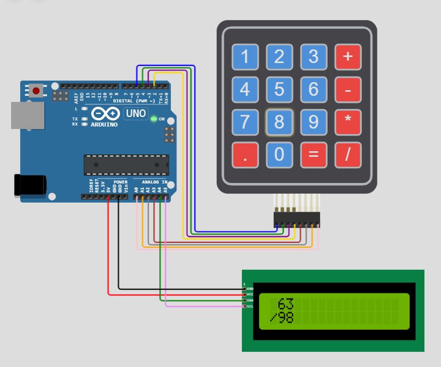
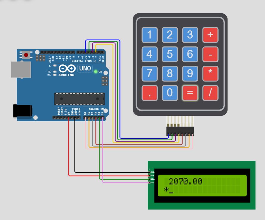
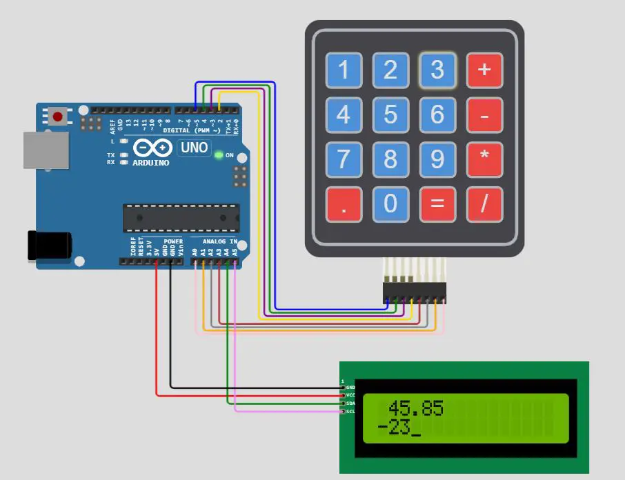
Result
The results of the calculations are included in the demonstration which includes subtraction, multiplication and division. After the input, the keyboard has to press the subtract, multiply or division buttons then enter a new value and press equal.
What’s Next
Please find more tutorials on Arduino in peppe8o Arduino archives.
Enjoy!
Umar Jamil
For any queries and help with work, please contact me at:
Whatsapp: +92-346-661-7017/ Link
Email: umarjamil0007@gmail.com

I'm an Electronic Engineer, well-skilled to solve the issues of hardware and software. I do have laboratory which contains unlimited sensors and modules for testing the working. Also, I am experienced in Arduino programming, Android mobile application, microcontroller programming, IOTs and embedded projects. I provide services to control, realize the sensor data in the Mobile Application. For any queries and help for work Contact: Whatsapp:+92-346-661-7017 Email: umarjamil0007@gmail.com
![]()


