
Last Updated on 3rd March 2023 by peppe8o
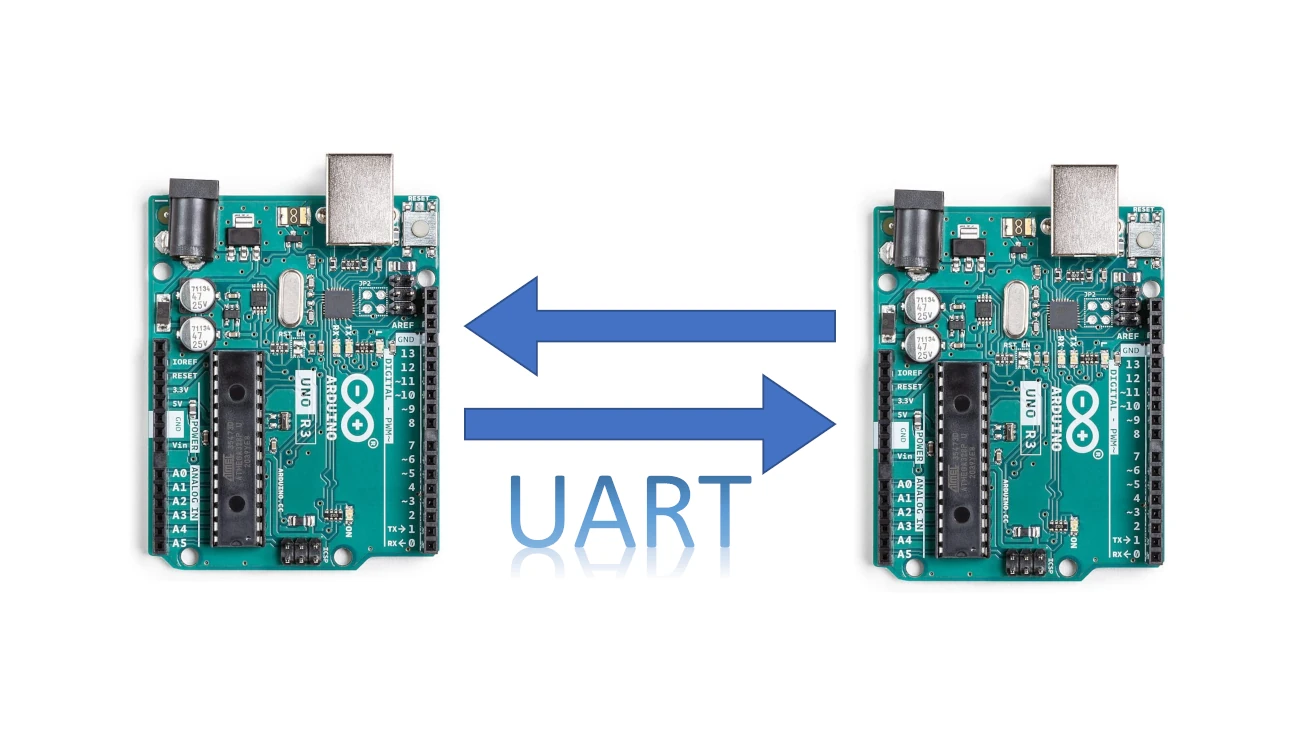
In this tutorial, we will use two Arduino Uno to communicate with each other via Arduino UART (universal asynchronous receiver-transmitter) communication. This communication is a type of serial communication, also known as USART.
This tutorial helps hardware and software engineers create a wired connection between the devices by using fewer wires.
UART Introduction
UART is a type of serial communication protocol that allows two devices to exchange data over a single communication line with serial communication.
UART uses two wires for communication: a transmit line (TX) and a receive line (RX). From a wiring point of view, the Rx of the second microcontroller connects with the Tx of the first. When one device wants to send data to the other, it transmits a series of bits over the TX line, with each bit being sent sequentially. The receiving device then reads these bits from the RX line and interprets them as data.
The UART uses the common non-return-to-zero (NRZ) format while sending and receiving. Data is transmitted as a series of bits, with each bit representing either a “0” or a “1”. These bits are transmitted one at a time, with a fixed duration between each bit to allow the receiver to correctly interpret the data.
One of the key features of UART is that it is an asynchronous protocol. This means that there is no fixed timing relationship between the sender and receiver and that each device can transmit data at its own pace. To perform this, UART uses a start bit and stop bit to indicate the beginning and end of each data transmission. Every character transmission starts with a start bit and then has five to nine bits of transmitted data before ending with one or more stop bits. Both the Begin and Stop parts are always spaces or marks. The stop bit also notifies the receiver that the data transmission is complete, and allows the receiver to prepare for the next transmission.
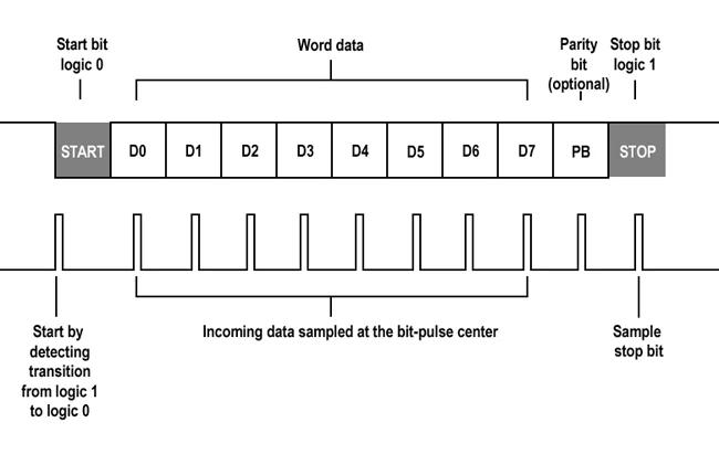
Every bit transmitted lasts 1/second (Baud Rate). An on-chip specialized baud rate generator is used by the system oscillator to generate standard baud rate frequencies.
UART also allows for different configurations, such as the number of data bits per transmission, the parity bit used for error checking, and the baud rate, which determines the speed of data transmission. These settings need to be the same on both devices to ensure successful communication.
Overall, UART is a reliable and widely-used communication protocol that is simple to implement and works well for many applications.
What We Need
As usual, I suggest adding from now to your favourite e-commerce shopping cart all the needed hardware, so that in the end you will be able to evaluate overall costs and decide if continue with the project or remove them from the shopping cart. So, hardware will be only:

- two Arduino Uno Boards
- Dupont wirings
- 2 switch buttons
- 2 LED
- resistors
- breadboard (optional)
Step-by-Step Procedure
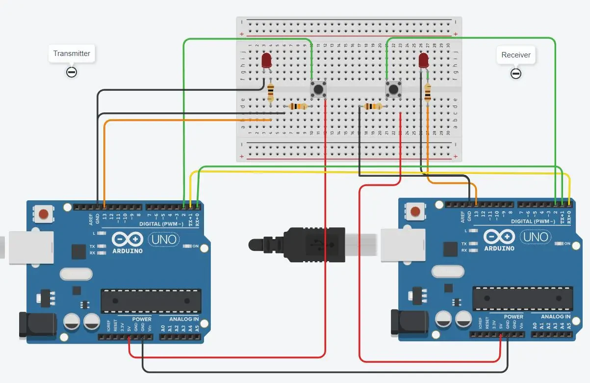
Arduino UART Communication Wiring Diagram
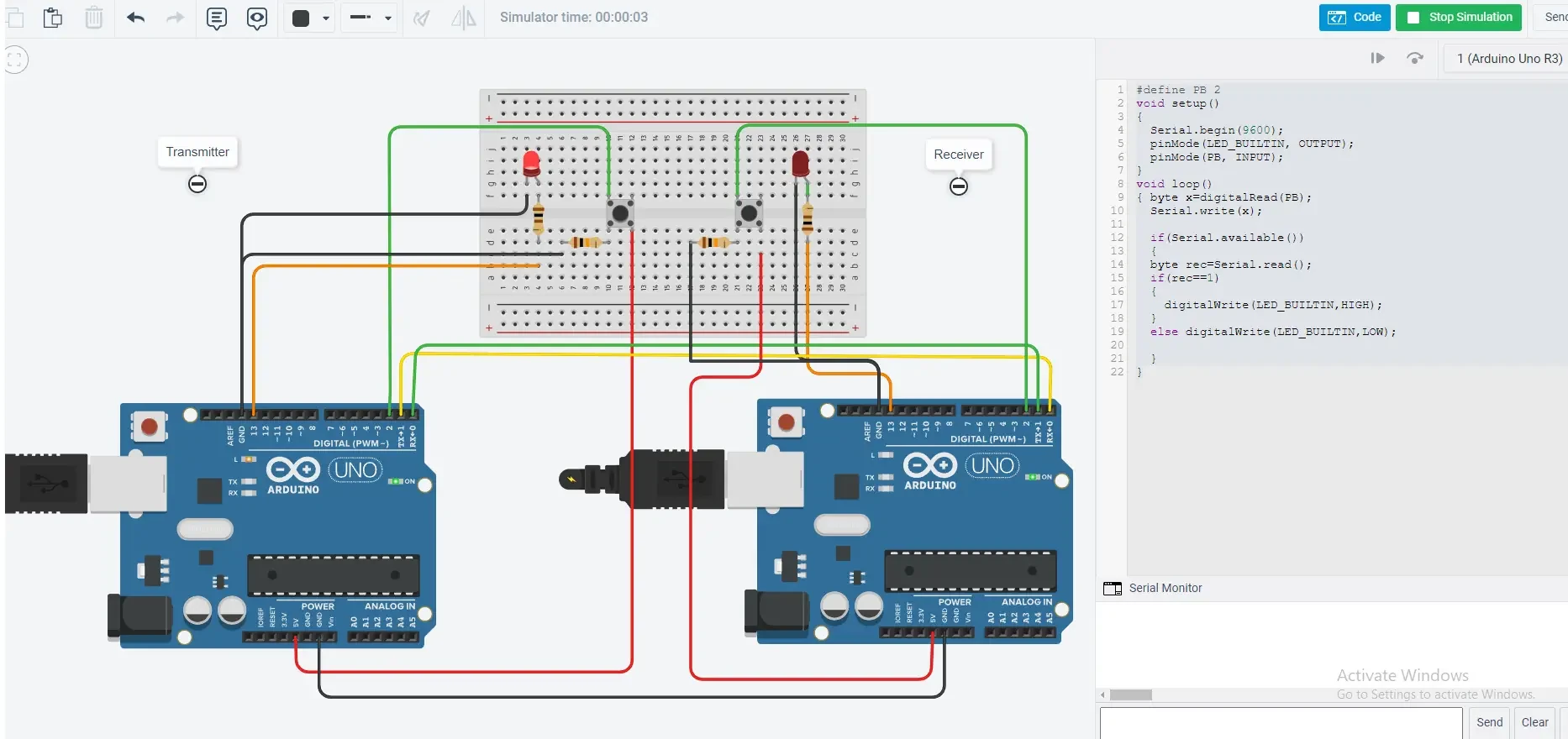
The project’s main goal is to link the two Arduino boards through UART TX (transmitter) and RX (receiver). It’s vital to note that TX in Arduino 1 links to RX in Arduino 2 so that when one device communicates, the other will listen, and vice versa.
Arduino Uno 1 >> Arduino uno 2
- Connect Ground to Ground
- Connect the TX pin Arduino 1 to the RX of the Arduino 2
- Connect the RX pin Arduino 1 to the TX of the Arduino 2
Get the code for communication between the two Arduinos
Connect your PC to the Arduino board and open the Arduino IDE. For the very first steps, you can refer to the Connecting Windows PC with Arduino tutorial. The “.ino” codes are available in my download area via the following link:
Code Explanation
Section 1: “uart-trasmitter-code.ino” code
This section contains the code explanation for the transmitter, which performs Serial.write(x). The x is the value that reads from the push button. The push button, when pressed, becomes high, which means that it becomes 1. The baud rate set for the communication is 9600. The LEDs are set here to get the value from the receiver to turn the LED on and off.
#define PB 2
void setup()
{
  Serial.begin(9600);
  pinMode(13, OUTPUT);
  pinMode(PB, INPUT);
}
void loop()
{ byte x=digitalRead(PB);
  Serial.write(x);
  if(Serial.available())
  {
  byte rec=Serial.read();
  if(rec==1)
  {
    digitalWrite(13,HIGH);
  }
  else digitalWrite(13,LOW);
  }
}
Section 2: “uart-receiver-code.ino” code
This is the section for the receiving part. Both the receiving and transmitting codes look the same as the communication is happening in half-duplex. So the commands send from the transmitter and received at the receiver by the serial.read() if the value is 1, then the LED turns on; otherwise, it remains off.
#define PB 2
void setup()
{
Serial.begin(9600);
pinMode(13, OUTPUT);
pinMode(PB, INPUT);
}
void loop()
{ byte x=digitalRead(PB);
Serial.write(x);
if(Serial.available())
{
byte rec=Serial.read();
if(rec==1)
{
digitalWrite(13,HIGH);
}
else digitalWrite(13,LOW);
}
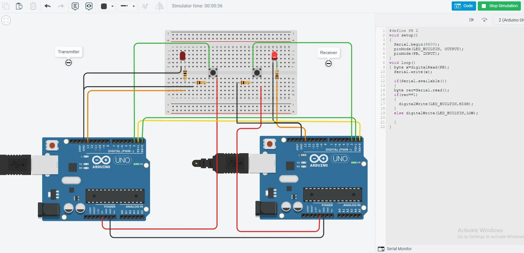
}Simulating the Arduino UART communication
The simulation is made to give the demo, as in the picture it can be seen that the led on the receiver side is on, which happened by pressing the button at the transmitter. Similarly, the second figure, displays that LED is on the transmitter side, in which the button at the receiver is pressed. On pressing the button, the value becomes 1, which means that the transmitted value is 1, while without pressing the button, the value is 0.
What’s Next
Please find more tutorials on Arduino in peppe8o Arduino archives.
Enjoy!
Umar Jamil
For any queries and help for work, please contact me at:
Whatsapp: +92-346-661-7017/ Link
Email: umarjamil0007@gmail.com

I'm an Electronic Engineer, well-skilled to solve the issues of hardware and software. I do have laboratory which contains unlimited sensors and modules for testing the working. Also, I am experienced in Arduino programming, Android mobile application, microcontroller programming, IOTs and embedded projects. I provide services to control, realize the sensor data in the Mobile Application. For any queries and help for work Contact: Whatsapp:+92-346-661-7017 Email: umarjamil0007@gmail.com
![]()


