Last Updated on 22nd March 2026 by peppe8o
This post will show you how to use the Raspberry PI Robot HAT by SunFounder.
This board allows you to simplify how your Raspberry PI computer board controls your DIY robot project, by adding a layer able to control sensors and motors.
The SunFounder uses it, for example, in their PiDog, a Raspberry PI Robot Dog.
Please note that, at the date of this post, the Raspberry PI Robot HAT by SunFounder doesn’t support Raspberry PI OS Bookworm. So, also the Raspberry PI 5 is not supported. Considering that robot projects don’t require so much computing power, you can use it with an older Raspberry PI computer board, up to RPI 4 model B.
About the SunFounder Robot HAT for Raspberry PI
Robot HAT Specs
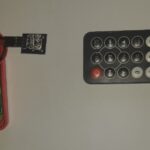
The SunFounder robot HAT comes in a package including a battery module, made of 2x 18650 batteries, standoffs and 2 cables for DC motors. There are also spare standoffs so that, if you lose or break one of them, you don’t need to be worried about ordering again a tiny plastic part. The main features of the robot HAT follows in the list below:
- Power Input: USB Type-C, 5V/2A
- Charging Power: 5V/2A 10W
- Output Power: 5V/3A
- Included Batteries: 2 x 3.7V 18650 Lithium-ion Batteries, XH2.0 3P Interface
- Battery Protection: Reverse polarity protection
- Charging Protection: Input undervoltage protection, input overvoltage protection, charging balance, overheat protection
- Onboard Charging / Power Indicators
- Onboard Battery Level Indicators
- Motor Driver: 5V/1.8A x 2
- 4-channel 12-bit ADC
- 12-channel PWM
- 4-channel digital signals
- Onboard SPI interface, UART interface, I2C interface
- Mono Speaker: 8Ω1W
Moreover, please find below the main electrical values:
| Parameters: | Minimum Value | Typical Value | Maximum Value | Unit |
|---|---|---|---|---|
| Input Voltage: | 4.25 | 5 | 8.4 | V |
| Battery Input Voltage: | 6.0 | 7.4 | 8.4 | V |
| Overcharge Protection (Battery): | 8.3 | V | ||
| Input Undervoltage Protection: | 4.15 | 4.25 | 4.35 | V |
| Input Overvoltage Protection: | 8.3 | 8.4 | 8.5 | V |
| Charging Current (5V): | 2.0 | A | ||
| Output Current (5V): | 3.0 | A | ||
| Output Voltage: | 5.166 | 5.246 | 5.327 | V |
| Charging Overheat Protection: | 125 | 135 | 145 | °C |
| DC-DC Overheat Protection: | 70 | 75 | 80 | °C |
| Motor Output Current: | 1.8 | A |
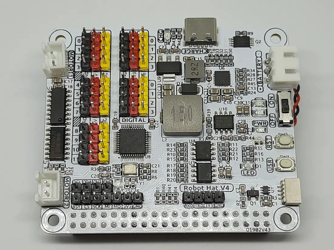
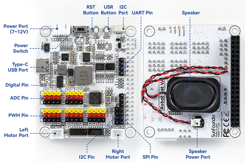
Robot HAT Ports
The robot HAT has its own PINs to connect external devices via PWM, Analogic, Digital, and serial ports, besides 2 ports specifically designed for. It also includes power ports to input current from the battery pack and from an external power source.
Power Ports
You can use the USB-C port to connect an external power source. In this way, your robot HAT will take power from the external source and recharge the battery pack. The device also includes electronics to keep the current coming from the external source safe and avoid problems while charging the battery:
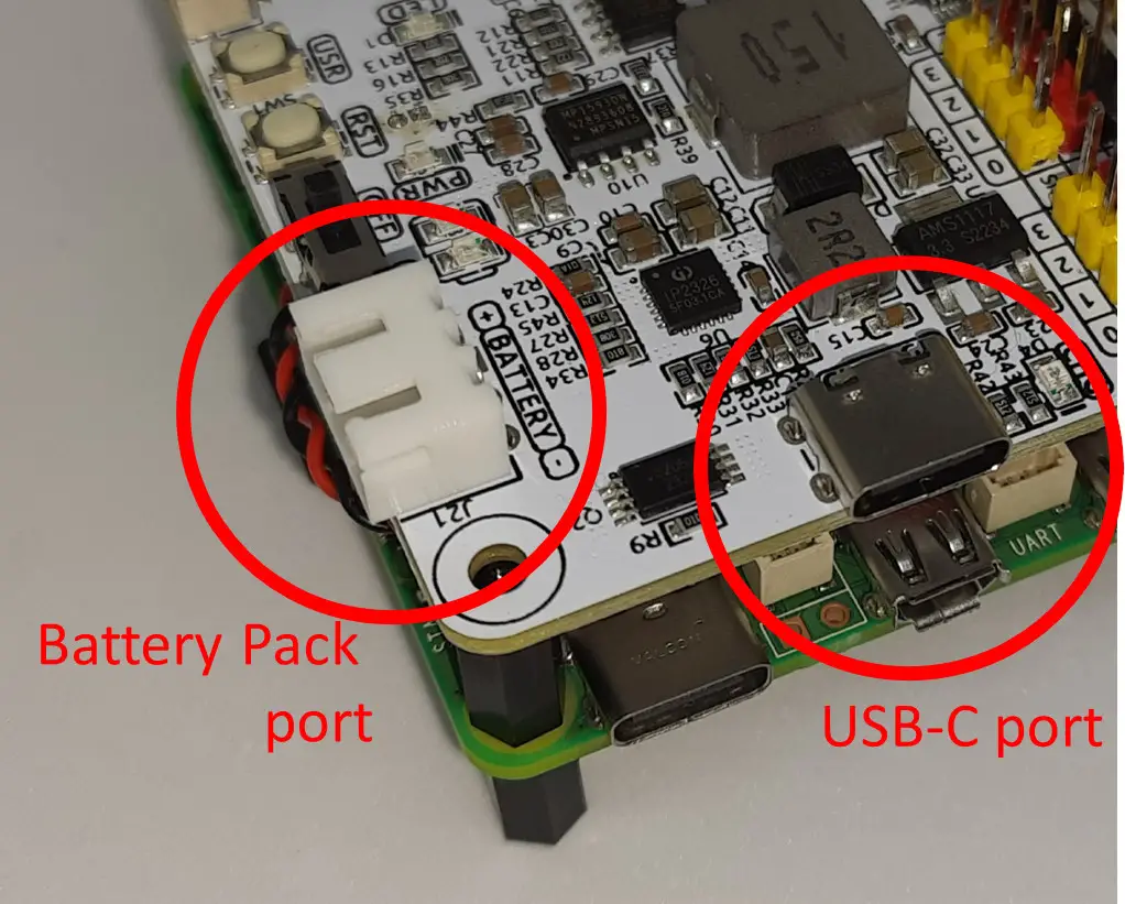
The switch near the battery pack port will allow you to enable the Robot HAT and power the Raspberry PI, without the need to use a second power supply to power the computer board.
Digital PINs
There are 4 digital PINs in the Robot HAT:
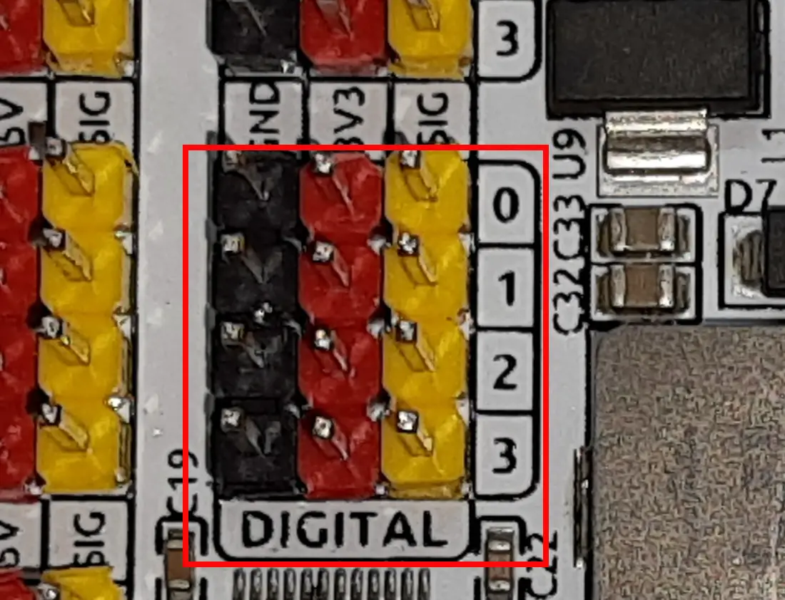
These PINs are mapped directly to 4 Raspberry PI PINs, according to the following table:
| Robot Hat V4 | Raspberry Pi |
|---|---|
| D0 | GPIO17 |
| D1 | GPIO4 |
| D2 | GPIO27 |
| D3 | GPIO22 |
So, you can manage these PINs as you would without the HAT, keeping in consideration the matching table above.
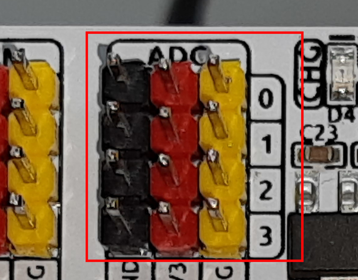
Analog PINs
The lack of analog PINs has been a great limitation for all of the Raspberry PI computer boards over the years. The robot HAT allows you to get 4 analog PINs (from channel 0 to channel 3), controlled by the on-board AT32F415CBT7 microcontroller from Artery. They provide a 12-bit precision (from 0 to 4095), which samples the 3.3V operating range. Tip of this board, the charge level of the battery pack can be measured with a “hidden” analogic channel 4.
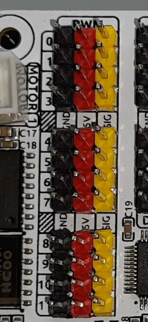
PWM PINs
Robots usually make large use of servo motors (like the SG90) or DC motors whose speed can be controlled via Pulse Witdh Modulation signals. The robot HAT takes care of this need by providing 12x PWM PINs:
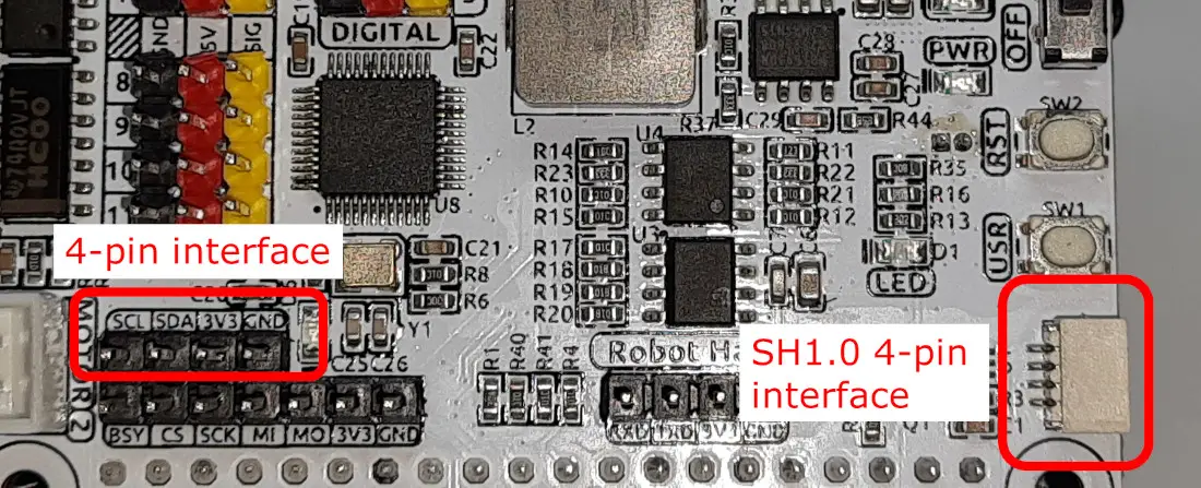
I2C PINs
There are 2x I2C interfaces. The first one comes with classic wiring PINs (4-PINs) and the other one comes with an SH1.0 interface. The second one is useful for devices coming with QWIIC and STEMMA QT connectors.
Both of them are connected to the Raspberry PI GPIO2 (SDA) and GPIO3 (SCL).
SPI PINs
Also, SPI PINs are provided by the robot HAT, with a 7-PIN interface:
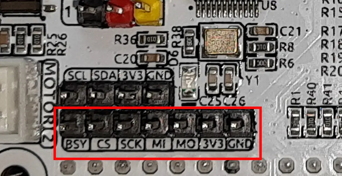
The PIN mapping table follows:
| Robot Hat V4 | Raspberry Pi |
|---|---|
| BSY | GPIO6 |
| CS | CE0(GPIO8) |
| SCK | SCLK(GPIO11) |
| MI | MISO(GPIO9) |
| MO | MOSI(GPIO10) |
| 3V3 | 3.3V Power |
| GND | Ground |
UART PINs
The same method is for the UART interface (4-pin), even if the UART connection is becoming less used compared to the other ports.
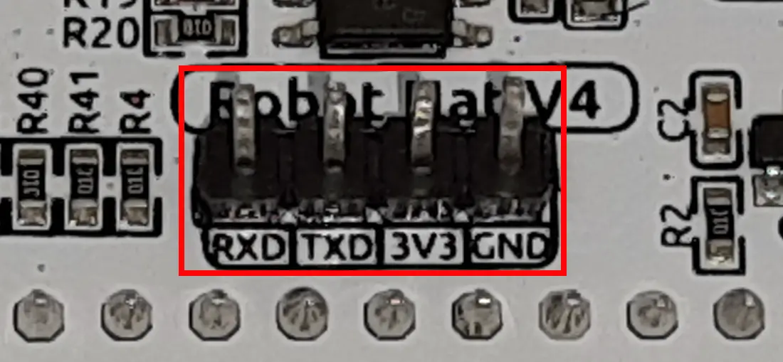
It connects to the Raspberry Pi’s GPIO14 (TXD) and GPIO15 (RXD) pins.
Motor Ports
With the Raspberry PI Robot HAT, there are 2 ports which are explicitly deputed to manage motors:
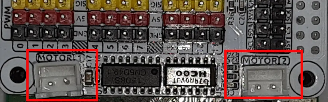
The speed and direction of motors can be managed by using 2 Raspberry PI GPIO PINs (for the direction) and 2 “hidden” PWM channels from the Robot HAT:
| Motor | IO |
|---|---|
| Motor1 Dir | GPIO23 |
| Motor1 Power | PWM13 |
| Motor2 Dir | GPIO24 |
| Motor2 Power | PWM12 |
However, the SunFounder Python libraries will make the use of the motors simpler.
Robot HAT Buttons
There are 2 buttons available at the top of the board. The USR button can be customised according to your needs, while the RST button is available for customisation only when not using the SunFounder Ezblock app:
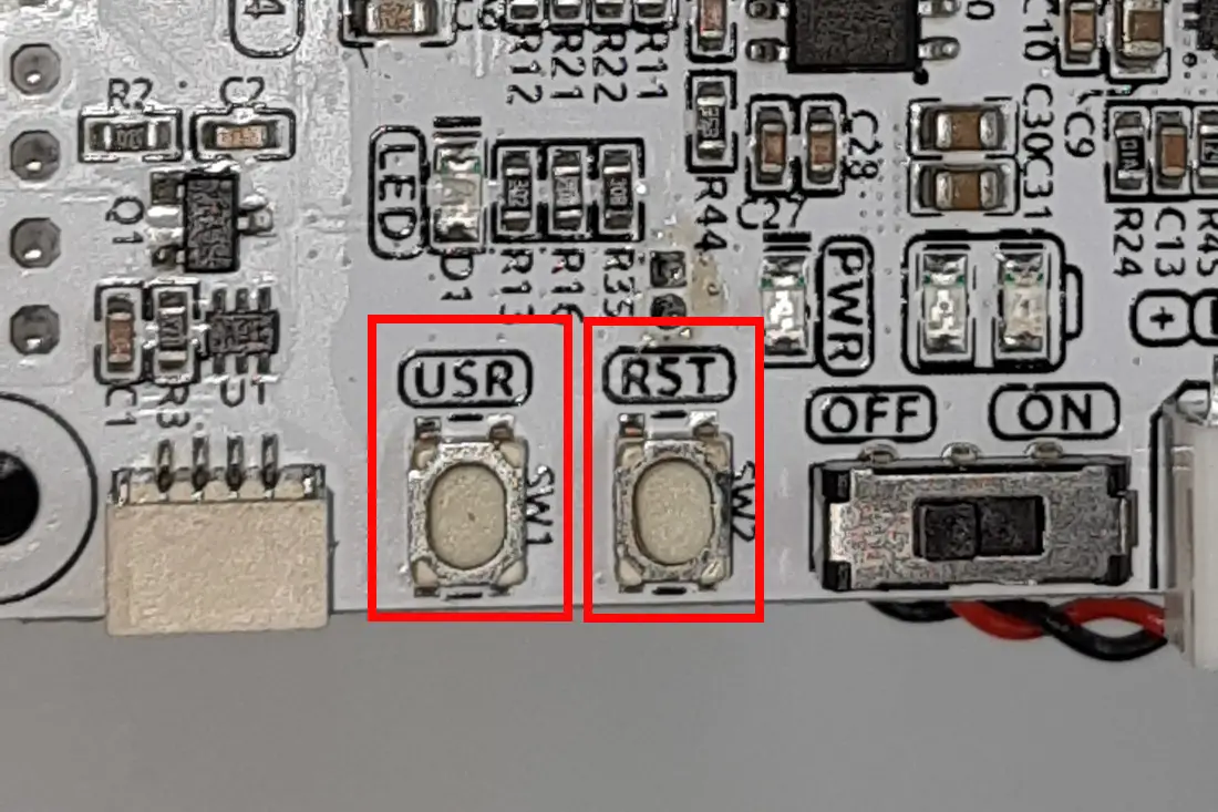
There is also an LED near the USR button. You can manage it from the Raspberry PI GPIO26. The table of button mapping follows:
| Robot Hat V4 | Raspberry PI |
|---|---|
| LED | GPIO26 |
| USR | GPIO25 |
| RST | GPIO16 |
Robot HAT Speaker
Finally, there is also a 2030 audio chamber speaker in the backplane of the board:
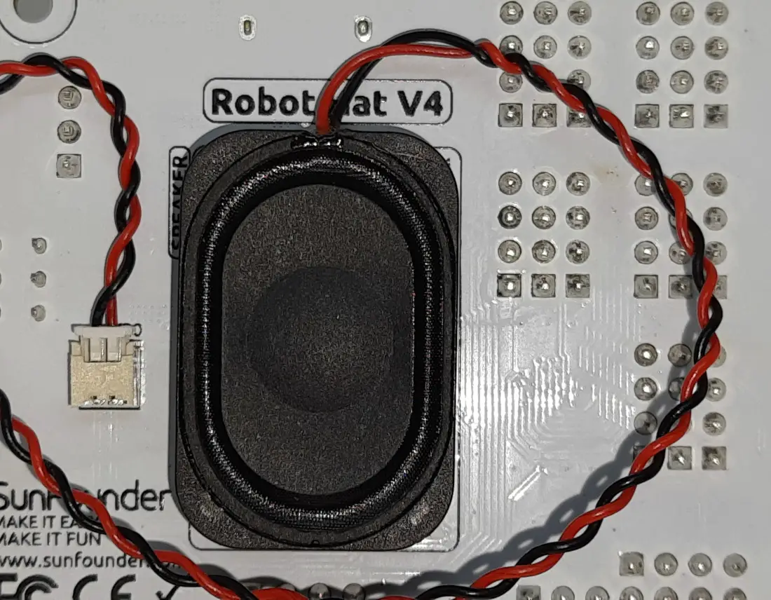
This can produce audio outputs via an I2S connection using the following PINs:
| I2S | Raspberry Pi |
|---|---|
| LRCLK | GPIO19 |
| BCLK | GPIO18 |
| SDATA | GPIO21 |
Robot HAT PIN mapping
The following table summarises the mapping between the Raspberry PI and Robot HAT PINs:
| Robot Hat V4 | Raspberry PI | Robot Hat V4 | Raspberry PI |
|---|---|---|---|
| NC | 3V3 | 5V | 5V |
| SDA | SDA | 5V | 5V |
| SCL | SCL | GND | GND |
| D1 | GPIO4 | TXD | TXD |
| GND | GND | RXD | RXD |
| D0 | GPIO17 | I2S BCLK | GPIO18 |
| D2 | GPIO27 | GND | GND |
| D3 | GPIO22 | MOTOR 1 DIR | GPIO23 |
| NC | 3V3 | MOTOR 2 DIR | GPIO24 |
| SPI MOSI | MOSI | GND | GND |
| SPI MISO | MISO | USR BUTTON | GPIO25 |
| SPI SCLK | SCLK | SPI CE0 | CE0 |
| GND | GND | NC | CE1 |
| NC | ID_SD | NC | ID_SC |
| MCU Reset | GPIO5 | GND | GND |
| (SPI)BSY | GPIO6 | Board Identifier 2 | GPIO12 |
| Board Identifier 1 | GPIO13 | GND | GND |
| I2S LRCLK | GPIO19 | RST BUTTON | GPIO16 |
| USER LED | GPIO26 | NC | GPIO20 |
| GND | GND | I2S SDATA | GPIO21 |
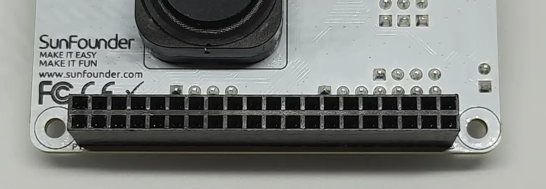
Mounting the Raspberry PI Robot HAT
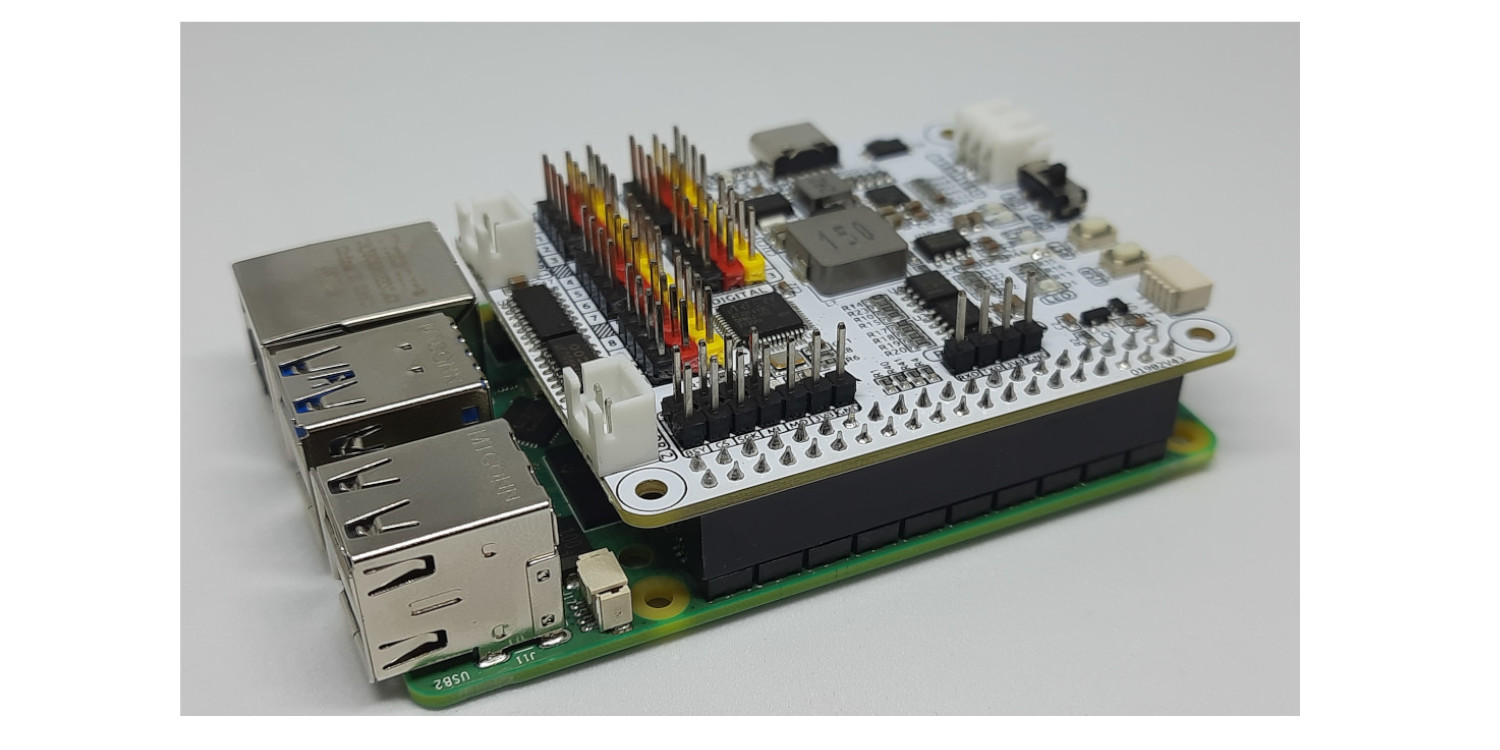
The Robot HAT board matches the Raspberry PI computer board heading to be placed directly on top of it. So, you don’t have to use cabling and check complicated pinout mapping to connect the robot HAT: its female header under the board will perfectly match your Raspberry PI computer board header (only for Raspberry PI models with 40-pin header, which means all the Raspberry PI models from 2 onward).
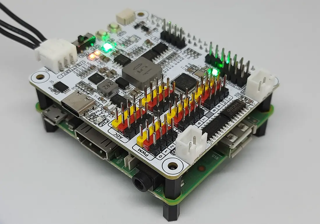
There’s no risk of mounting it on the wrong side, once you see the board mounted as in the following picture:
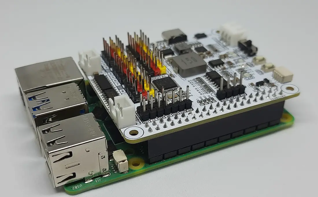
As you can see, it is highly compact and easy to manage. The board also comes with standoffs (not shown in the previous picture), so it will be fixed when connecting cables from your sensors and motors.
What We Need
To use the Robot HAT, we need a few pieces:
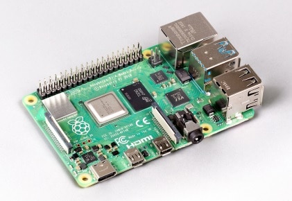
- Raspberry PI Computer Board 2, 3, or 4 (including proper power supply or using a smartphone micro USB charger with at least 3A). The robot HAT should also work with Raspberry PI Zero w/2W, even if 2 of the 4 standoffs will not fit on the RPI because it’s smaller.
- SunFounder Robot HAT, also available from the SunFounder Store
- high-speed micro SD card (at least 16 GB, at least class 10)
- Dupont wirings, motors, sensors (according to your project needs)
Test the Robot HAT
For my tests, I’m going to use a Raspberry PI 3 model A+. I love this board because it’s a great compromise between the computing power of a Raspberry PI model B, the low power consumption of a Raspberry PI Zero W, and the price close to the Raspberry Pi Zero W one! Moreover, it fits well with the robot HAT:
Anyway, the following test will also work with the newer Raspberry PI computer boards.
Prepare the Operating System
Start preparing your Operating System. You can install the fast Raspberry PI OS Lite (without a Desktop environment, but faster) or opt for Raspberry PI OS Desktop, using its internal terminal. You can find the differences in my Raspberry PI OS Lite vs Desktop: comparison between the 2 distributions.
IMPORTANT NOTE: As already mentioned, at the date of this post, the SunFounder Robot HAT is supported only with Debian Bullseye. So, you must use the “Legacy” Bullseye OS. I also suggest the 64-bit version.
Make sure your OS is up to date with the following commands:
sudo apt update -y && sudo apt upgrade -yWe also need to install some required packages:
sudo apt install git python3-setuptools python3-smbus python3-pip -yFinally, we can download the SunFounedr robot HAT libraries and install them:
git clone https://github.com/sunfounder/robot-hat.git -b v2.0
cd robot-hat
sudo python3 setup.py install
I also suggest installing the gpiozero package (if not already installed), as it will help in some of the following tests and, generally, for your projects:
sudo apt install python3-gpiozeroThe last installation step regards the i2s amplifier package, still coming inside the robot-hat folder:
sudo bash i2samp.shTesting the LED
In this test, we’ll make the robot HAT on-board LED blink. We’ll control it directly from the Raspberry PI PINs, as the LED is connected to the GPIO26 as before explained.
Let’s create a new file from the Raspberry PI terminal:
nano led_test.pyPaste the following code, which will simply turn on and off the LED every 1 second:
from gpiozero import LED
from time import sleep

led = LED(26)

try:
  while True:
    led.on()
    sleep(1)
    led.off()
    sleep(1)

except KeyboardInterrupt:
  led.off()
  print("Ending program")
Close and save (CTRL + X). Run the test with the following terminal command:
python3 led_test.pyThe LED will start blinking. You can stop the test at any time with CTRL+D.
Testing an SG90 Servo Motor
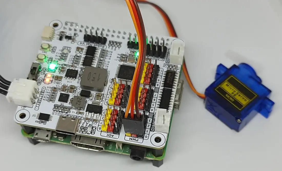
SG90 servo motors usually come with a 3-wire connector bringing GND, VCC and signal. They work with a PWM signal and should perfectly fit the PWM connectors. In my test, I will connect my PWM 0 channel:
Let’s create a new test file. From terminal:
nano sg90test.pyPaste the following code. As you can see below, the code is really simple as, after initialising the servo ports, you can control a specific servo motor angle with the command “servos[<<ch_number>>].angle()”:
from robot_hat import Servo
import time

# Create objects for 12 servos
servos = [Servo(f"P{i}") for i in range(12)]

def initialize_servos():
    """Set initial angle of all servos to 0."""
    for servo in servos:
        servo.angle(-90)
        time.sleep(0.1)  # Wait for servos to reach the initial position
    time.sleep(1)

# Initialize servos to their initial position
initialize_servos()

# Control servos
servos[0].angle(0)
time.sleep(0.5)
servos[0].angle(90)
time.sleep(0.5)
servos[0].angle(-90)
time.sleep(0.5)
Save and close this file (CTRL+X). You can run it with the following command:
python3 sg90test.pyIt will initialise the servo motor to the -90 angle. Then it will move into 3 different positions with a pause of 0.5 seconds between each move.
Testing the Speaker
The Speaker test can be the most fun for kids. The SunFounder library comes with a text-to-speech function, which enables you to let your robot speak. Please create a robot_tts.py file:
nano robot_tts.pyPaste the following code. You can see there that, after initialising the TTS language (en-US in the test), you can directly pass your sentence to the tts.say() method. Moreover, this test will close by printing all the supported languages:
import sys
from robot_hat import TTS

# Check if there are enough command line arguments
if len(sys.argv) > 1:
    text_to_say = sys.argv[1]  # Get the first argument passed from the command line
else:
    text_to_say = "Hello peppe8o"  # Default text if no arguments are provided

# Initialize the TTS class
tts = TTS(lang='en-US')

# Read the text
tts.say(text_to_say)

# Display all supported languages
print(tts.supported_lang())
Close and save.
When running this test, you can pass the sentence via the terminal command, inside brackets:
python3 robot_tts.py "hello!"If nothing is specified, it will produce the default test available in the code. As said, the test will also end, showing the supported languages:
pi@raspberrypi:~ $ python3 robot_tts.py "hello!"
['en-US', 'en-GB', 'de-DE', 'es-ES', 'fr-FR', 'it-IT']
SunFounder Robot HAT Docs
The full documentation about the robot HAT is available at the SunFounder official docs page.
What’s Next
Interested in more cool ways to use your Raspberry PI computer board? Take a look at peppe8o Raspberry PI computer tutorials!
Enjoy!

Open source and Raspberry PI lover, writes tutorials for beginners since 2019. He's an ICT expert, with a strong experience in supporting medium to big companies and public administrations to manage their ICT infrastructures. He's supporting the Italian public administration in digital transformation projects.
![]()
![]()
![]()
![]()
![]()
![]()
![]()