
Last Updated on 2nd September 2023 by peppe8o
In this tutorial, we’ll interface the current sensor (ACS712) with Arduino Uno, dealing with current sensing and utilization for current control. This tutorial provides the coding, wiring diagram and component list.
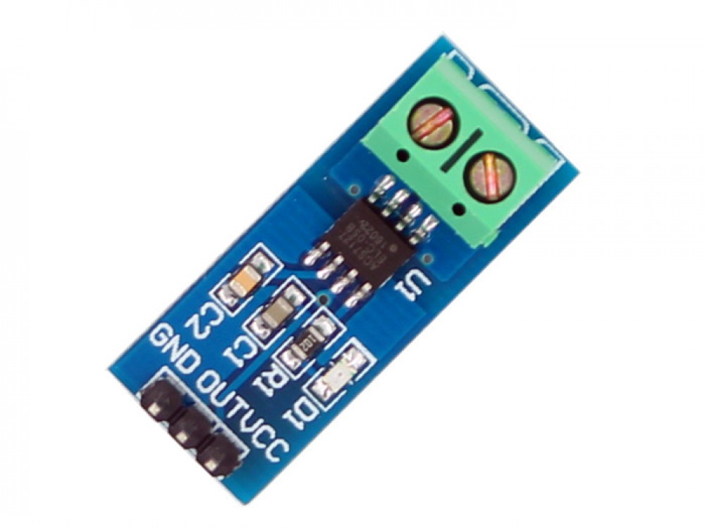
To measure the current passing through the wire, ACS712 is the best current sensor to deal with, as it can measure up to 5A
Current Sensor Introduction
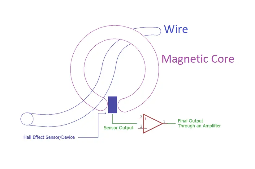
In industrial, commercial, and communications systems, the ACS712 provides cost-effective and precise AC or DC current sensing solutions. The circuit is made up of a precise, low-offset linear Hall circuit with a copper conduction route near the die’s surface. The Hall IC converts the magnetic field generated by the applied current flowing via this copper conduction route into a proportionate voltage. The magnetic signal is close to the Hall transducer, which improves device accuracy.
Working Principle of Current Sensor
The ACS712 generates an analogue signal from the Vout pin. The Vout voltage fluctuates linearly with the uni- or bi-directional AC or DC primary sampled current. The noise is removed by adding a capacitor and inductor filter with values that vary depending on the application. The signal leads are electrically insulated from the conductive path’s terminals optocoupler. This enables the ACS712 utilize in applications that require electrical isolation without the use of expensive opto-isolators or other isolation techniques.
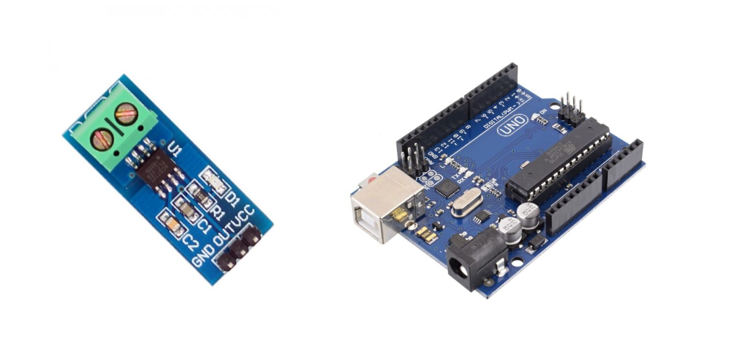
What We Need
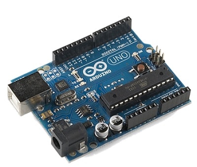
As usual, I suggest adding from now to your favourite e-commerce shopping cart all the needed hardware, so that at the end you will be able to evaluate overall costs and decide if to continue with the project or remove them from the shopping cart. So, hardware will be only:
Check hardware prices with the following links:


Step-by-Step Procedure
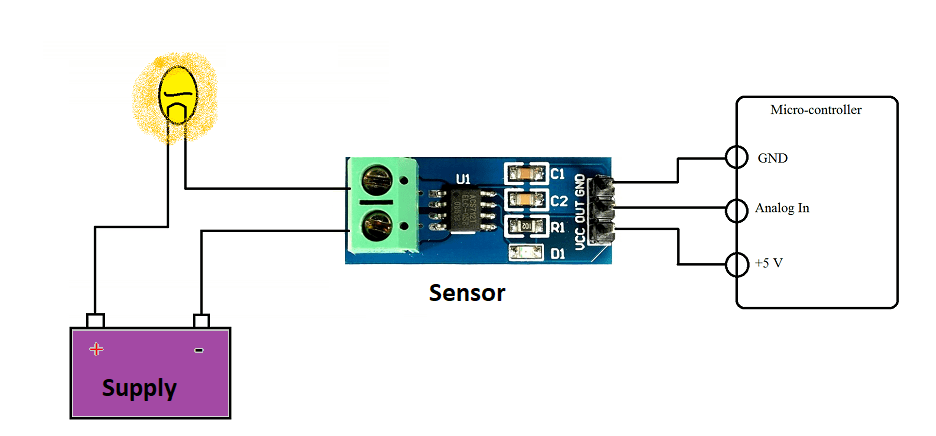
Wiring Diagram of Current Sensor with Arduino
There are 3 pins of the current sensor, VCC connects to the +5V, Ground Connect with the GND and OUT connects with the A0 of the Arduino Uno. The current sensor is an analogue, which value varies from 0 to 5V.
Get currentsensor.ino, Code Explanation
Connect your PC to Arduino and open Arduino IDE. For the very first steps, you can refer to Connecting Windows PC with Arduino tutorial. Get the current Sensor code from the download area with the link:
Code Explanation Section
Section 1: Current sensor and Acsvalue variables are declared for displaying and reading the current values. Setup starts in which the baud rate of the serial monitor is set at 9600.
float currentvalue = 0.0f; // current display variable
float AcsValue = 0.0f; // current reading variable
/**************************
 * Start of Setup
 **************************/
void setup()
{
  Serial.begin(9600);
}
Section 2: Reading of the sensor perform from pin A0.
As explained in code comments, the formula implements the following measure:
current_value = mean_voltage_error – (sensor_value * (max_voltage / resolution_steps)) /voltage_change_per_Ampere.
Then, we print the read voltage and the current value on serial monitor.
/**************************
* Start of Loop
**************************/
void loop() {
AcsValue = analogRead(A0);
currentvalue = (2.5 - (AcsValue * (5.0 / 1024.0)) ) / 0.185;
// 2.5 is the voltage of mean error so needs to be seperated.
// AcsValue is the current sensor value.
// 5/1024 are the number of steps.
// 0.185 is the voltage change per 1 amperes.
// currentvalue= meanvoltageerror - (sensorvalue * (voltage/resolution))/ voltage change per Ampere
Serial.print("initialValue: ");
Serial.print(AcsValue);
Serial.println("mV");
Serial.print(currentvalue*1000);
Serial.print("mA");
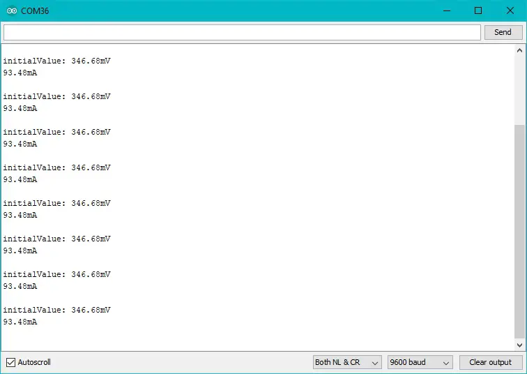
}Results
In the serial monitor, the voltage produces by the sensor display. Voltage and current displays on the serial monitor to see the resemblance of the values.
Important Note: (I don’t recommend this if you are not well ) This sensor can measure up to 5A. To increase the current measurement change the Resistor R1 on the sensor and replace it with a shunt: just connect it the same as the terminal of the resistor removed. Each end of the terminal with each side of the resistor pad on the sensor. R1 resistor must be removed when adding the shunt.
What’s Next
Please find more tutorials on Arduino in peppe8o Arduino archives.
Enjoy!
Umar Jamil
For any queries and help for work, please contact me at:
Whatsapp: +92-346-661-7017/ Link
Email: umarjamil0007@gmail.com

I'm an Electronic Engineer, well-skilled to solve the issues of hardware and software. I do have laboratory which contains unlimited sensors and modules for testing the working. Also, I am experienced in Arduino programming, Android mobile application, microcontroller programming, IOTs and embedded projects. I provide services to control, realize the sensor data in the Mobile Application. For any queries and help for work Contact: Whatsapp:+92-346-661-7017 Email: umarjamil0007@gmail.com
![]()


