
Last Updated on 13th April 2024 by peppe8o
In this tutorial, I’ll show you how to interface the water level sensor with Arduino Uno. This tutorial will explain the coding, connection diagram, and components list required for doing it. If you have measured the water level in the tank and turned the motor off once it is full, or you have a leakage problem, a water level sensor is a solution to all your problems.
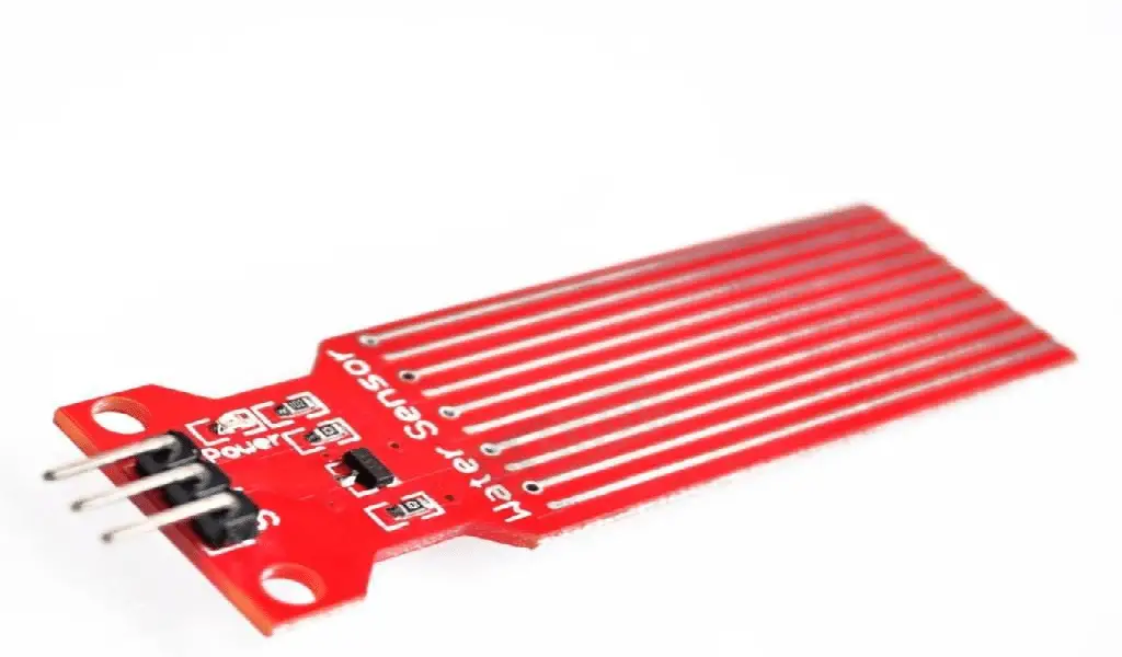
Features of Water Level Sensor
In order to measure the water level of the tank to avoid overflow. Water level sensor with Arduino Uno microcontroller is the best and cheap option.
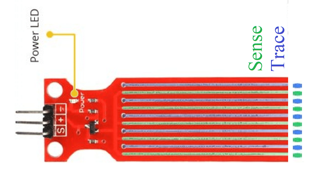
The sensor contains 10 traces of copper on its surface. Five out of ten copper traces are power traces and the rest of the five are sense traces. Traces are drawn in such a way that between every two power traces there lies a sense trace so each sense trace is sandwiched between the two power traces. These traces remain disconnected and water going up on surface creates a bridge. There is a power LED that turns on once power is supplied to the sensor. In the figure given below the blue traces are power traces and green ones represent sense traces.
Working Principle of Water Level Sensor
The working principle of the water level sensor is very simple. The traces or parallel lines are basically conductors which act together as a variable resistor just like a potentiometer. The resistance is varied in proportion to water level. Through this variation in resistance, you can measure the water level with the help of a microcontroller.
The change in resistance is in accordance with the distance from the top of the sensor to the water level which means that the resistance is maximum when the distance from the top of the sensor to the water level is maximum and when the distance is minimum the resistance is also minimum.
The resistance and height of water are inversely related.
- The more water goes up on the sensor surface, the higher conductivity goes and we get less resistivity.
- The lower water goes up on the sensor surface, the lower conductivity goes and we get higher resistivity.
Water Level Sensor Pinout
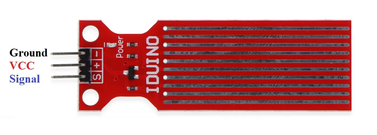
There are three pins on the water level sensor which make it easy to use.
Signal Pin: This pin is an analog output pin, which is connected to the analog input of the microcontroller to read the value of the water level.
VCC Pin: This pin is indicated by the plus sign (+). It is connected to a 5volt pin on the microcontroller.
Ground Pin: This pin carries the negative sign (-) with it. You’ll connect it to the ground pin of Arduino.
What We Need
As usual, I suggest adding from now to your favourite e-commerce shopping cart all the needed hardware, so that at the end you will be able to evaluate overall costs and decide if to continue with the project or remove them from the shopping cart. So, hardware will be only:
Check hardware prices with following links:


Wiring Diagram
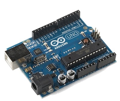
In order to connect the water level sensor with Arduino, please arrange wiring that, according to Arduino Uno Pinout, will be compliant with the following picture. The Vcc or + should be connected with the 5v pin on Arduino. Ground or (–) should be connected with the ground pin on Arduino. The signal pin or (S) should be connected with any analog pin on Arduino.
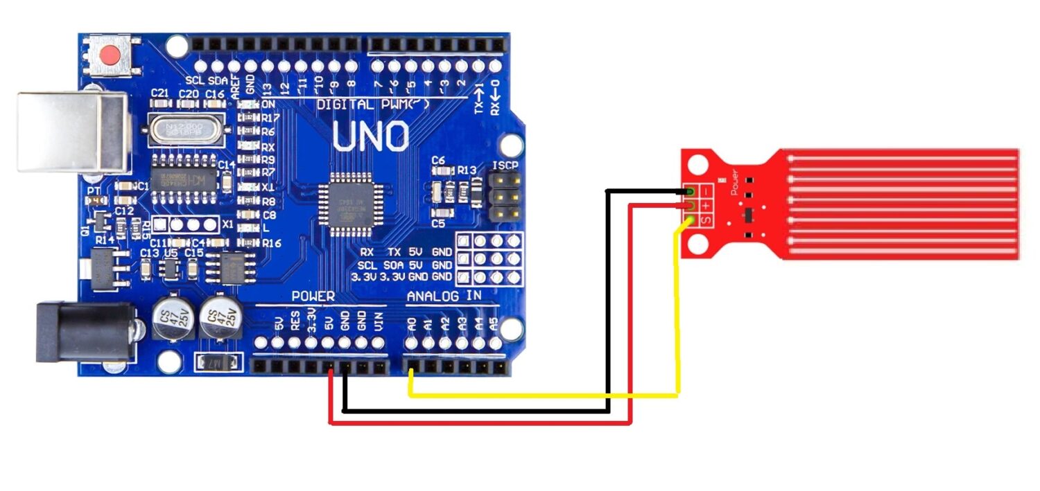
Please find below the connection table:
| PIN No. | PIN Name | Purpose |
| 1. | Ground | Ground PIN >> Connect to 0V or GND |
| 2. | VCC | Voltage PIN >> Connect to +5V |
| 3. | Signal pin | Output >> Connect with an Analog PIN. |
Step by Step Code Explanation
The Water Level Sensor Code
Connect your PC to Arduino and open Arduino IDE. For the very first steps, you can refer to Connecting Windows PC with Arduino tutorial. Get the .ino code from my download area with the following link:
Extract it and open the “.ino” file in your Arduino IDE. Please find below a brief code description.
In the beginning, we define PIN. We use the analog pin A0 for the sensor pin where we connected the data for the water level sensor.
#define sensorPin A0
int val = 0;
We initialize the serial monitor at a baud rate of 9600. To see the data, we must also set COM port serial monitor at a 9600 baud rate.
Serial.begin(9600);With the following function, we store the value of the sensor in the “level” variable. Then, we print the value of level on the serial monitor using the next line.
void loop() {
  int level = analogRead(sensorPin);
  level = map (level, 0, 1023, 0 , 100);
  Serial.print("Water level: ");
  Serial.print(level);
  Serial.println("%");
  delay(1000);
}
Compile and upload the code, and you will start looking the measured values on serial monitor.
Enjoy!
Please find more tutorials on Arduino in peppe8o Arduino archives.
Umar Jamil
For any queries and help for work, please contact me at:
Whatsapp: +92-346-661-7017
Email: umarjamil0007@gmail.com

I'm an Electronic Engineer, well-skilled to solve the issues of hardware and software. I do have laboratory which contains unlimited sensors and modules for testing the working. Also, I am experienced in Arduino programming, Android mobile application, microcontroller programming, IOTs and embedded projects. I provide services to control, realize the sensor data in the Mobile Application. For any queries and help for work Contact: Whatsapp:+92-346-661-7017 Email: umarjamil0007@gmail.com
![]()


This can also be done with just a single transistor and power supply etc. Although I recommend using 2 stainless wires as sensor to avoid corrosion.