
Last Updated on 17th March 2023 by peppe8o
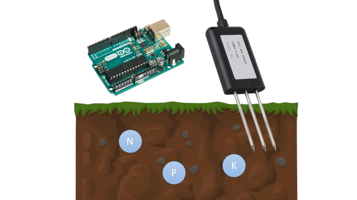
In this tutorial, we will use Arduino, an NPK soil sensor to get the soil fertility. The percentage of nitrogen, Phosphorus and Potassium is measured using the probe sensor.
Introduction
NPK Soil Sensor and Arduino make it simple to measure the nutrient content of the soil. To calculate how much extra nutrient content needs to be supplied to the soil to raise crop fertility, the N, P, and K contents of the soil must be measured. The soil NPK sensor can be used to measure the soil nitrogen, phosphorus, and potassium concentrations. It facilitates the systematic evaluation of the soil condition by assisting in assessing the soil’s fertility. To ensure the long-term functionality of the probe component, it should be of high quality so that it is resistant to corrosion due to soil salts and pH effects.
What We Need

As usual, I suggest adding from now to your favourite e-commerce shopping cart all the needed hardware, so that at the end you will be able to evaluate overall costs and decide if to continue with the project or remove them from the shopping cart. So, hardware will be only:
Step-by-Step Procedure
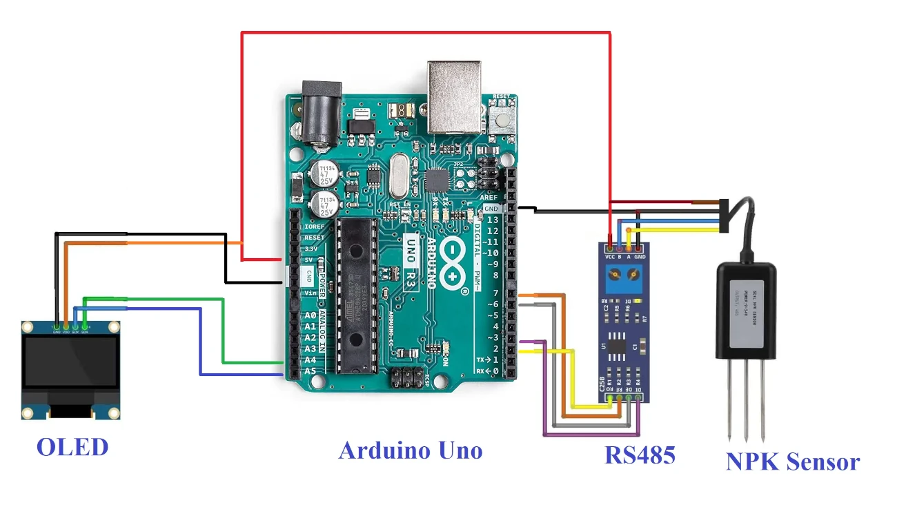
Wiring Diagram of NPK soil sensor with Arduino
The figure represents the wiring diagram soil sensor and OLED with Arduino Uno. The voltage applied to the soil sensor should be 5V.
The Soil sensor and OLED with the Arduino connect in this pattern.
RS485 >> Soil sensor
- Connect Ground to Ground
- Connect the VCC pin to the 5V of the Arduino
- Connect the R0 pin to Arduino pin 2
- Connect the DI pin to Arduino pin 3.
- Connect the RE pin to Arduino pin 7.
- Connect the DE pin to Arduino pin 6.
RS485 >> Arduino Uno
- Connect Ground to Ground
- Connect the VCC pin to the Arduino 5v pin
- Connect the third pin to pin B of the RS485 module
- Connect the third pin to pin B of the RS485 module
- Connect the fourth pin to pin A of the RS485 module
OLED >> Arduino Uno
- Connect Ground to Ground
- Connect the VCC pin to the Arduino 5v pin
- Connect SCK pin to Arduino pin A5
- Connect the SDA pin to Arduino pin A4.
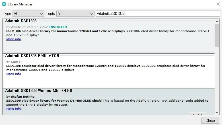
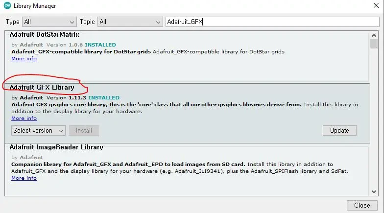
Get the code and OLED Libraries
Connect your PC to Arduino and open Arduino IDE. For the very first steps, you can refer to Connecting Windows PC with Arduino tutorial. You can get the .ino code and libraries from my download area with the following link:
You also need to install the following libraries, according to my Install Arduino Libraries: methods to add libraries with Arduino IDE tutorial.
npk-sensor-arduino.ino Explanation
Section 1
This is the section before setup which we’ll use for global variables definition and libraries addition.
Software serial.h is the library for performing serial communication.
Wire.h library is for the I2C communication enabling OLED.
Adafruit_GFX is the graphics library for the OLED
Adafruit_SSD1306.h is the communication library for the OLED.
#include <SoftwareSerial.h>
#include <Wire.h>
#include <Adafruit_GFX.h>
#include <Adafruit_SSD1306.h>
In the beginning, we define the width and height of the OLED. The RESET value is set to -1, while normally not required. The child for OLED creates the name of the display.
#define SCREEN_WIDTH 128  // OLED display width, in pixels
#define SCREEN_HEIGHT 64  // OLED display height, in pixels
#define OLED_RESET -1     // Reset pin # (or -1 if sharing Arduino reset pin)
Adafruit_SSD1306 display(SCREEN_WIDTH, SCREEN_HEIGHT, &Wire, OLED_RESET);
RE and DE pins define communication with the RS485 module.
#define RE 8
#define DE 7
The 3 arrays are created for the nitrogen, phosphorus and potassium in order to send commands to the sensor through the RS485 module.
const byte nitro[] = { 0x01, 0x03, 0x00, 0x1e, 0x00, 0x01, 0xe4, 0x0c };
const byte phos[] = { 0x01, 0x03, 0x00, 0x1f, 0x00, 0x01, 0xb5, 0xcc };
const byte pota[] = { 0x01, 0x03, 0x00, 0x20, 0x00, 0x01, 0x85, 0xc0 };
The variable creates for getting the value, while the softwareserial child creates with the name of the mod.
byte values[11];
SoftwareSerial mod(2, 3);
Section 2
This is the setup section in which Serial.begin(9600) initialize. mod.begin(9600) uses to initialize the connection with the RS485 module.
void setup() {
  Serial.begin(9600);
  mod.begin(9600);
Pinmodes defines as the RE and DE pins.
  pinMode(RE, OUTPUT);
  pinMode(DE, OUTPUT);
OLED initialize with the display.begin command along with its I2C address of 0x3C. We clear the OLED display to refresh the whole frame.
  display.begin(SSD1306_SWITCHCAPVCC, 0x3C);  //initialize with the I2C addr 0x3C (128x64)
  delay(500);
  display.clearDisplay();
The cursor is set and the text is set to 1 while the display colour is white.
  display.setCursor(25, 15);
  display.setTextSize(1);
  display.setTextColor(WHITE);
After that give the text to display, while display appears after display.display() command executes.
  display.println(" NPK Sensor");
  display.setCursor(25, 35);
  display.setTextSize(1);
  display.print("Initializing");
  display.display();
  delay(3000);
}
Section 3
In the loop section, we get the values of the nitrogen, phosphorus, and potassium by calling the following functions. Then we display them on the serial monitor as well as on the OLED:
void loop() {
  byte val1, val2, val3;
  val1 = nitrogen();
  delay(250);
  val2 = phosphorous();
  delay(250);
  val3 = potassium();
  delay(250);

  Serial.print("Nitrogen: ");
  Serial.print(val1);
  Serial.println(" mg/kg");
  Serial.print("Phosphorous: ");
  Serial.print(val2);
  Serial.println(" mg/kg");
  Serial.print("Potassium: ");
  Serial.print(val3);
  Serial.println(" mg/kg");
  delay(2000);
  display.clearDisplay();
  display.setCursor(0, 0);
  display.print("N: ");
  display.print(val1);
  display.print(" mg/kg");
  display.setCursor(0, 8);
  display.print("P: ");
  display.print(val2);
  display.print(" mg/kg");
  display.setCursor(0, 16);
  display.print("K: ");
  display.print(val3);
  display.print(" mg/kg");
  display.setCursor(0, 25);
  display.display();
  delay(2000);
}
With the following 3 functions, the commands will fill the array (already declared before in the setup) with nitro[], phos[] and pota[] to give the value of the nitrogen, phosphorus and potassium. In the loop, these values are returned as the results, stored in the value[] array.
byte nitrogen() {
  digitalWrite(DE, HIGH);
  digitalWrite(RE, HIGH);
  delay(10);
  if (mod.write(nitro, sizeof(nitro)) == 8) {
    digitalWrite(DE, LOW);
    digitalWrite(RE, LOW);
    for (byte i = 0; i < 7; i++) {
      values[i] = mod.read();
      Serial.print(values[i], HEX);
    }
    Serial.println();
  }
  return values[4];
}

byte phosphorous() {
  digitalWrite(DE, HIGH);
  digitalWrite(RE, HIGH);
  delay(10);
  if (mod.write(phos, sizeof(phos)) == 8) {
    digitalWrite(DE, LOW);
    digitalWrite(RE, LOW);
    for (byte i = 0; i < 7; i++) {
      values[i] = mod.read();
      Serial.print(values[i], HEX);
    }
    Serial.println();
  }
  return values[4];
}

byte potassium() {
  digitalWrite(DE, HIGH);
  digitalWrite(RE, HIGH);
  delay(10);
  if (mod.write(pota, sizeof(pota)) == 8) {
    digitalWrite(DE, LOW);
    digitalWrite(RE, LOW);
    for (byte i = 0; i < 7; i++) {
      values[i] = mod.read();
      Serial.print(values[i], HEX);
    }
    Serial.println();
  }
  return values[4];
}
Results
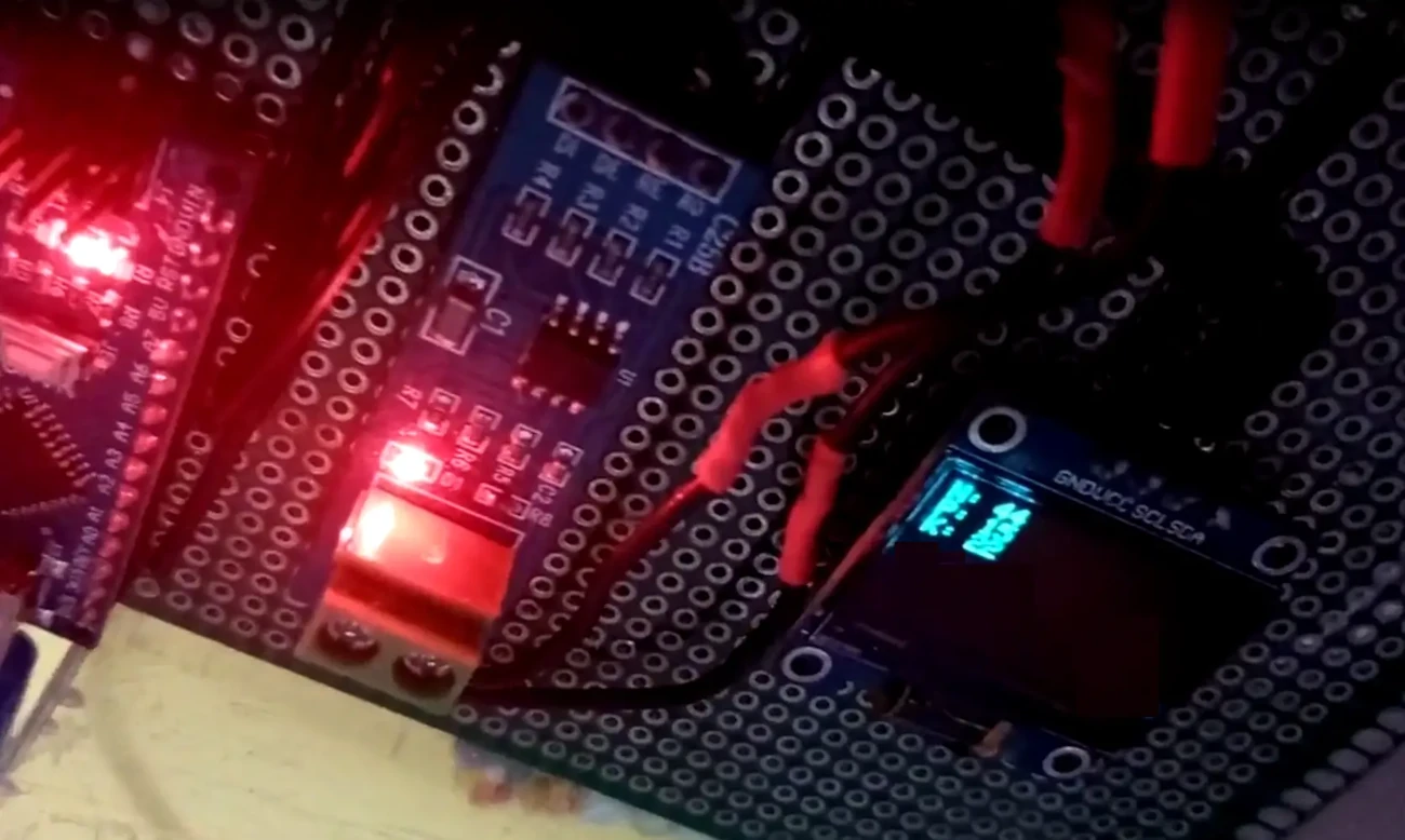
The results display the output of the soil sensor on the OLED. The Nitrogen (N), Phosphorus (P) and Potassium (K) measured by the sensor are printed on the OLED. The value of the N=44, P=15 and K =22.
What’s Next
Please find more tutorials on Arduino in peppe8o Arduino archives.
Enjoy!
Umar Jamil
For any queries and help for work, please contact me at:
Whatsapp: +92-346-661-7017/ Link
Email: umarjamil0007@gmail.com

I'm an Electronic Engineer, well-skilled to solve the issues of hardware and software. I do have laboratory which contains unlimited sensors and modules for testing the working. Also, I am experienced in Arduino programming, Android mobile application, microcontroller programming, IOTs and embedded projects. I provide services to control, realize the sensor data in the Mobile Application. For any queries and help for work Contact: Whatsapp:+92-346-661-7017 Email: umarjamil0007@gmail.com
![]()


