Last Updated on 9th June 2024 by peppe8o
In this tutorial, we are going to learn how to use a piezo buzzer with Arduino Uno by using Arduino IDE software.
Many projects (like melody) need to get audio notification which includes music and sound alert. In this logic, the most commonly used Arduino Uno device is the Piezo Buzzer
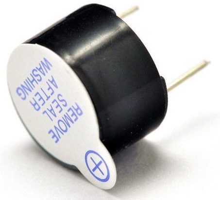
Buzzer Main Features
Piezo buzzer is another name for an Arduino buzzer. It is essentially a little speaker that you can connect directly to an Arduino. You may program it to emit a tone at a specific frequency. The buzzer generates sound by reversing the piezoelectric action. A buzzer, often known as a beeper, is a type of auditory signalling device that can be mechanical, electromechanical, or piezoelectric (piezo for short). Alarm devices, timers, and confirmation of human input such as a mouse click or keyboard are common applications for buzzers and beepers.
In its most basic form, a piezo buzzer is a sort of electrical device that emits a tone, alert, or sound. It’s lightweight, has a basic design, and is often inexpensive. However, depending on the piezo ceramic buzzer parameters, it is also dependable and may be built in a variety of sizes that function across varied frequencies to provide diverse sound outputs. A “piezo buzzer” is just a small speaker that can be directly connected to an Arduino.
Why Connect to PWM of Arduino?
When you apply electricity to some crystals, they change form. This is known as “piezoelectricity.” The crystal may produce sound by applying an electric signal at the appropriate frequency. Pull the sticker from the top of your buzzer if it has one. Connect one pin to the Arduino’s ground (Gnd) and the other end to digital pin 10. You can use tone to produce noises with a buzzer from the Arduino.
You must tell it which pin the buzzer is connected to, what frequency (in Hertz, Hz) you want, and how long (in milliseconds) you want the tone to last.
Due to the dependability and versatility of piezoelectric vibration plates in producing auditory signals ranging from monotone buzzes and alerts to multi-tones and melodies, their applications in a compact, high-density assemblies are numerous. Furthermore, because of their low power consumption, they are excellent for many battery-powered products. Piezo buzzers with similar properties are commonly employed in alarms, warning systems, and car alerts. Furthermore, because they can emit a wide variety of auditory sounds, they are utilized in pest deterrent systems. Sound generators are used in a variety of consumer electronics applications, including computers, cellphones, toys, and games, to mention a few.
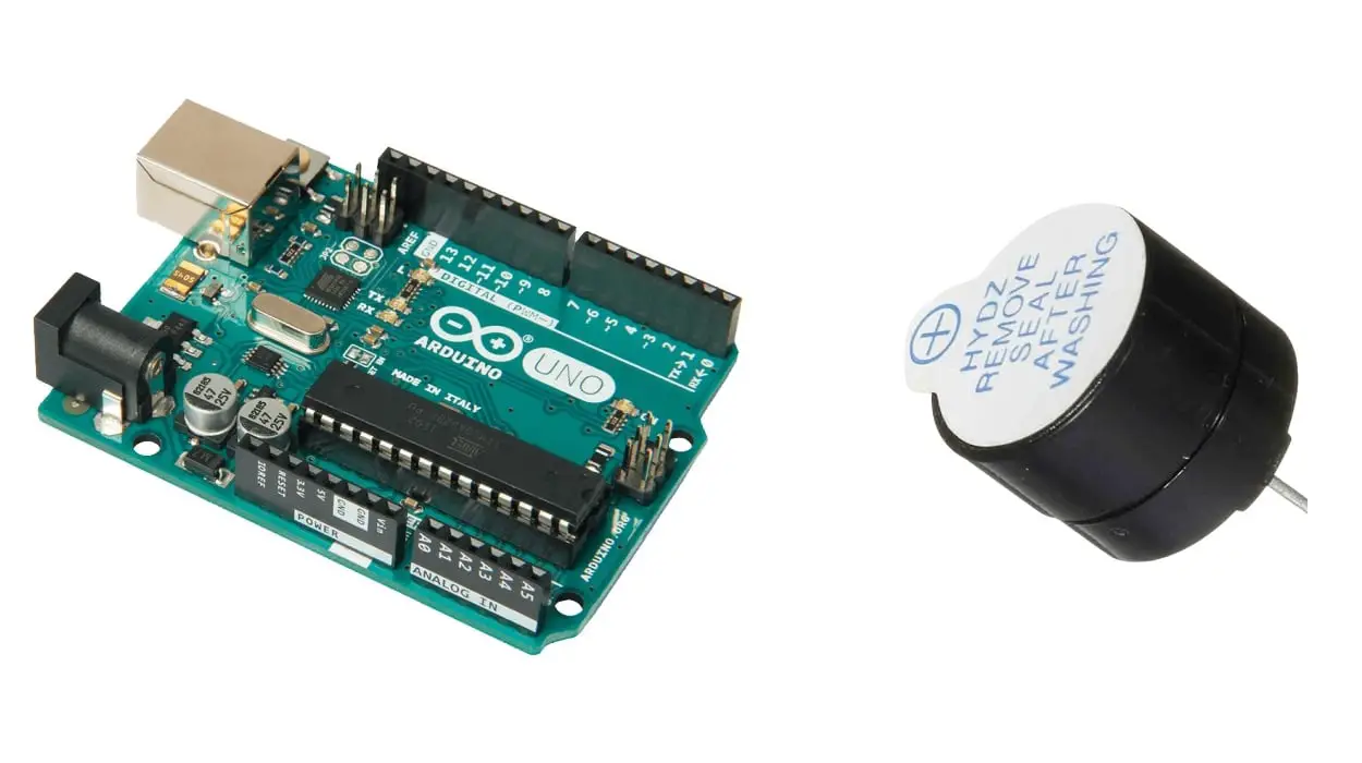
What We Need
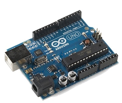
As usual, I suggest adding from now to your favourite e-commerce shopping cart all the needed hardware, so that at the end you will be able to evaluate overall costs and decide if to continue with the project or remove them from the shopping cart. So, hardware will be only:
Step-by-Step Procedure
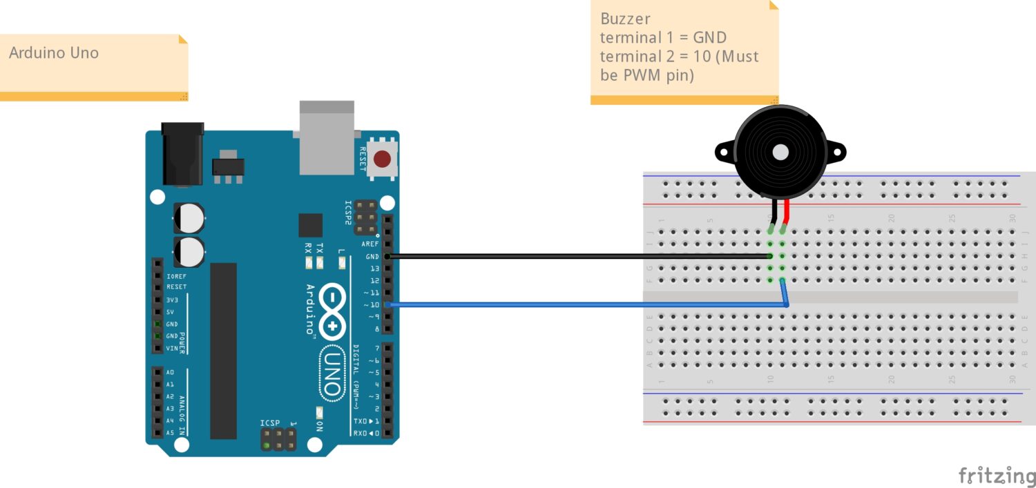
Buzzer Contains two pins, named as positive terminal and negative terminal. The positive terminal is usually mentioned with “+” sign on the back or front side of the buzzer. Positive needs to be connected at GPIO (PWM pin) of the microcontroller, while negative remain connected to ground (GND).
For this tutorial, I have connected the “+” terminal with PWM pin 10. While negative terminal at GND through breadboard as shown in the wiring diagram.
Wiring Diagram
Please connect your Arduino and buzzer according to the following picture:
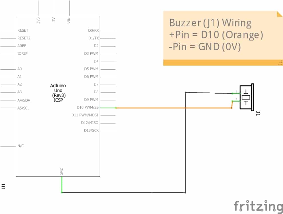
The following picture also shows circuit schematics:
Get the arduinobuzzer code
Connect your PC to Arduino and open Arduino IDE. For the very first steps, you can refer to Connecting Windows PC with Arduino tutorial.
Download the “arduinobuzzer” code from the following link:
Extract the folder from your PC. You will have a folder named “arduinobuzzer” containing a file named “arduinobuzzer.ino”. Open this file with your Arduino IDE.
Code Explanation
The first row creates a variable storing the PIN number matching the buzzer positive pole, for better code management and cleanness:
int buzzer = 10; // Pin DefinedThe setup area sets the buzzer PIN as output:
void setup()
{
pinMode ( buzzer, OUTPUT);  // Buzzer set as OUTPUT
}
The loop uses the Arduino tone() function which sets a PWM signal to buzzer PIN with the specified frequency, keeping it on for the specified duration:
void loop()
{
 tone(buzzer, 100, 1000); // (pin, frequency, duration time)
 delay(1000); // Wait for 1 second
Finally, the notone() function deactivates the PWM signal (so stopping the buzzer from sound emission). A final delay of 1 second adds a pause between each loop:
 noTone(buzzer); // Sound stop
 delay(1000); // Wait for 1 second
}
Run the Arduino Buzzer code
From your Arduino IDE, compile the code. Once compile operation has finished successfully, load it in your Arduino and you will start listening to the buzzer.
Enjoy!
Umar Jamil
For any queries and help for work, please contact me at:
Whatsapp:+92-346-661-7017
Email: umarjamil0007@gmail.com

I'm an Electronic Engineer, well-skilled to solve the issues of hardware and software. I do have laboratory which contains unlimited sensors and modules for testing the working. Also, I am experienced in Arduino programming, Android mobile application, microcontroller programming, IOTs and embedded projects. I provide services to control, realize the sensor data in the Mobile Application. For any queries and help for work Contact: Whatsapp:+92-346-661-7017 Email: umarjamil0007@gmail.com
![]()