
Last Updated on 13th April 2024 by peppe8o
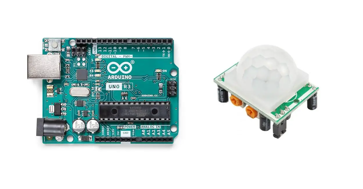
In this tutorial, I’m going to show you how to connect and setup Arduino Uno with a PIR sensor, Also examining its pinout, working, convention, and working protocol.
Detecting motion inside a monitoring area, such as security area or home restricted place, requires monitoring all the object moves within thas perimeter. The PIR sensor (HC-SR501) with Arduino is a good and cheap option, as it has ability to measure up to 7 meters
PIR Motion Sensor Description
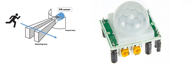
PIR sensor is used for security purposes to detect unauthorized persons or objects. There are two sensors inside the PIR sensor known as pyroelectric sensors which work on the heat energy changings, These two sensors sit adjacent to one another, and when the sign differential between the two sensors changes like assuming that an individual goes into the room or any object comes in the path. In front of the sensor is lenses housing which increases the sensing area.
PIR Motion Sensor Features
PIR sensor works on the basis of heat change: when the object is coming in front of it, the heat change is detected, then the PIR sensor send HIGH logic to the output pin. This sensor is normally used for lockers, unauthorized areas and home security. These are important features of the PIR Motion sensor, which includes its distancing, rays type and functionality description.
- The detecting distance of this sensor is from 25cm to 10 meters.
- Infrared radiations detected by heat energy change
- Detection Delay time adjusting from the Potentiometer on the backside of the sensor
- TTL logic as the output
What We Need
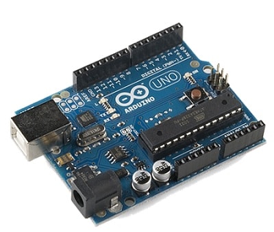
As usual, I suggest adding from now to your favourite e-commerce shopping cart all the needed hardware, so that at the end you will be able to evaluate overall costs and decide if to continue with the project or remove them from the shopping cart. So, hardware will be only:
Check hardware prices with the following links:


Step-by-Step Procedure
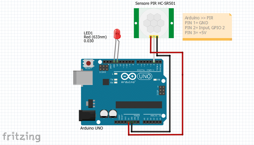
PIR Sensor contains 3 pins, which are VCC, Input pin and ground. In the connection diagram, you can see that GND is connected with Pin 1, the second pin is connected to Pin 2 and the third pin is connected to the VCC +5 volts. The output of the PIR sensor is HIGH and LOW which means it has zero or 5 volts.
Wiring Diagram
Please connect the PIR sensor to Arduino according to the following picture:
Please find below the connection table:
| PIN No. | PIN Name | Purpose |
| 1. | Ground | Ground PIN >> Connect to 0V or GND |
| 2. | Vout | Output >> Connect with an Digital GPIO PIN |
| 3. | VCC | Voltage PIN >> Connect to +5V |
Get my PIR sensor Code
Connect your PC to Arduino and open Arduino IDE. For the very first steps, you can refer to Connecting Windows PC with Arduino tutorial. Please download my PIR sensor code, by using the following link:
Extract it and open the .ino file in your Arduino IDE.
Code Explanation
PIR sensor pin is defined as a global variable and in the setup function, we set the baud rate at 9600 to initialise the serial monitor. This sets the transmission rate with our serial monitor so that we can display the performed measurements. PIR sensor pin is set as input for the microcontroller, LED is included in the code to turn on the LED when our sensor detects motion.
int pirPin = 2; // Sensor input pin
int ledPin = 13; // LED output pin
void setup() {
  Serial.begin(9600); // Serial Monitor Initialized
  pinMode(pirPin, INPUT); // PIR sensor pin set as input
  pinMode(ledPin, OUTPUT); //LED pin set as output
  digitalWrite(pirPin, LOW); // PIR sensor set low
  digitalWrite(ledPin, LOW); // LED OFF
}
In the following section, the PIR pin is read continuously. When an object comes then this pin becomes HIGH, which we detect as the object motion. This turns on the LED and shows on the serial monitor an “Object Detected” warning.
If no object is detected, then the LED remains OFF and the display on Serial Monitor will show the message “NO Object”.
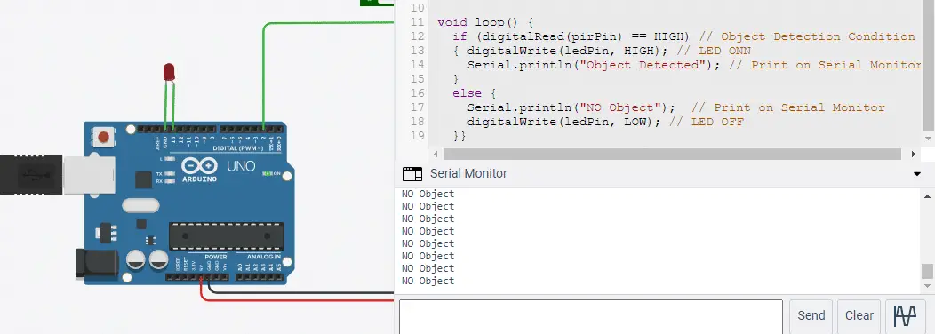
void loop() {
  if (digitalRead(pirPin) == HIGH) // Object Detection Condition
  { digitalWrite(ledPin, HIGH); // LED ONN
    Serial.println("Object Detected"); // Print on Serial Monitor
  }
  else {
    Serial.println("NO Object");  // Print on Serial Monitor
    digitalWrite(ledPin, LOW); // LED OFF
  }}
Results and Discussion
In the following picture, you can see that the serial monitor is showing no object when the sensor does not detect any object. LED is OFF as LED works only when an object is detected.
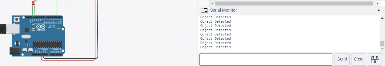
In this picture, the object is detected, which makes the LED turn ON, also displaying on the serial monitor “OBJECT DETECTED”.
Enjoy!
Please find more tutorials on Arduino in peppe8o Arduino archives.
Umar Jamil
For any queries and help for work, please contact me at:
Whatsapp: +92-346-661-7017
Email: umarjamil0007@gmail.com

I'm an Electronic Engineer, well-skilled to solve the issues of hardware and software. I do have laboratory which contains unlimited sensors and modules for testing the working. Also, I am experienced in Arduino programming, Android mobile application, microcontroller programming, IOTs and embedded projects. I provide services to control, realize the sensor data in the Mobile Application. For any queries and help for work Contact: Whatsapp:+92-346-661-7017 Email: umarjamil0007@gmail.com
![]()


