
Last Updated on 13th April 2024 by peppe8o
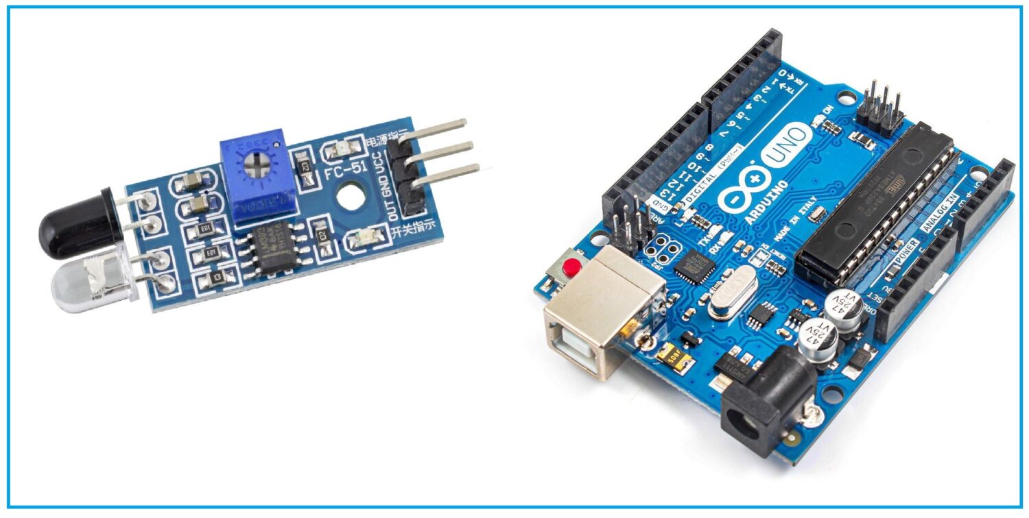
In this tutorial, we’ll interface the IR sensor with Arduino Uno including coding, connection diagram, and listing the components.
To make Line Following Robot and detection of object, IR sensor is best to use in such situation
IR Sensor Information
In order to be able to interface IR sensor with Arduino, it is necessary to understand what IR sensor actually is. IR stands for the infrared region. Sensors capable of working with that region of light are IR sensors. IR technology is widely used in industries and our daily life. For example in the TV remote, IR technology is used for the communication between the TV and it’s remote allowing the user to have a level of comfort by controlling the TV from a fair amount of distance rather than manual labour. Since the IR sensor uses low power that makes them user-friendly and uses widely.
In the electromagnetic spectrum, IR radiations lie in the visible and microwave region. The range of these waves is between 0.7 micrometers and 100 micrometers. IR spectrum can divide into three regions namely near-infrared, mid and far-infrared region. The range of near-infrared is between 0.7 and 3 micrometers. From 3 micrometer to 6 micrometer lies mid-infrared region and higher than 6 micrometer is a far-infrared region.
Features of IR sensor
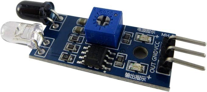
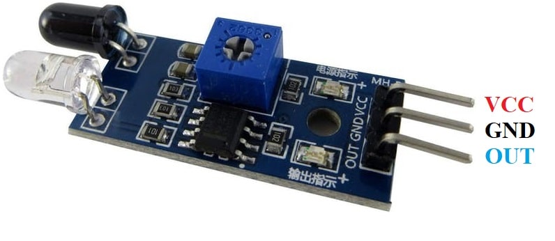
Consisting of three pins, a potentiometer, and two LEDs, the IR sensor is an electronic device that emits radiations in order to get a sense of the surrounding. IR sensor has the capability to measure the heat of the object and can also detect motion. Such types of sensors that get the sense of the surrounding by only detecting/receiving or absorbing IR radiations rather than emitting IR radiations are passive IR sensors.
The human eye cannot detect IR radiations but to IR sensor these radiations are visible. At the end of the module, there are two LEDs. One is RED led which performs the function of the emitter and the other one is photodiode which works as a receiver. The emitter emits infrared radiations which after hitting some object receives by the detector photodiode is sensitive only to the radiations of the infrared region. When the emitted IR radiations fall on the photodiode, it produces resistance and voltage which is in proportion to the radiations fell upon.
Working of IR Sensor
The working of IR sensors in the basic sense is similar to that of ultrasonic sensors because both of them involve a transmitter and receiver. The sensor constitutes of an IR LED and an IR photodiode. By appearance, IR LED is similar to that of standard LED and it works as a transmitter that transmits infrared radiations which are not visible to the human eye.
On receiving side there is a photodiode which is different from standard photodiodes. Usually, photodiodes are sensitive to any light but the IR photodiode which is used in IR sensor is sensitive only to infrared radiations emitted by IR LED. The infrared photodiode responsive to infrared radiations emitted by infrared LED transmitter, generates resistance or voltage which is in proportion to the number of infrared radiations received by IR photodiode. This change in resistance or voltage is sent to Arduino and thus the motion of an object or its distance measures. This is the fundamental working principle of the IR sensor.
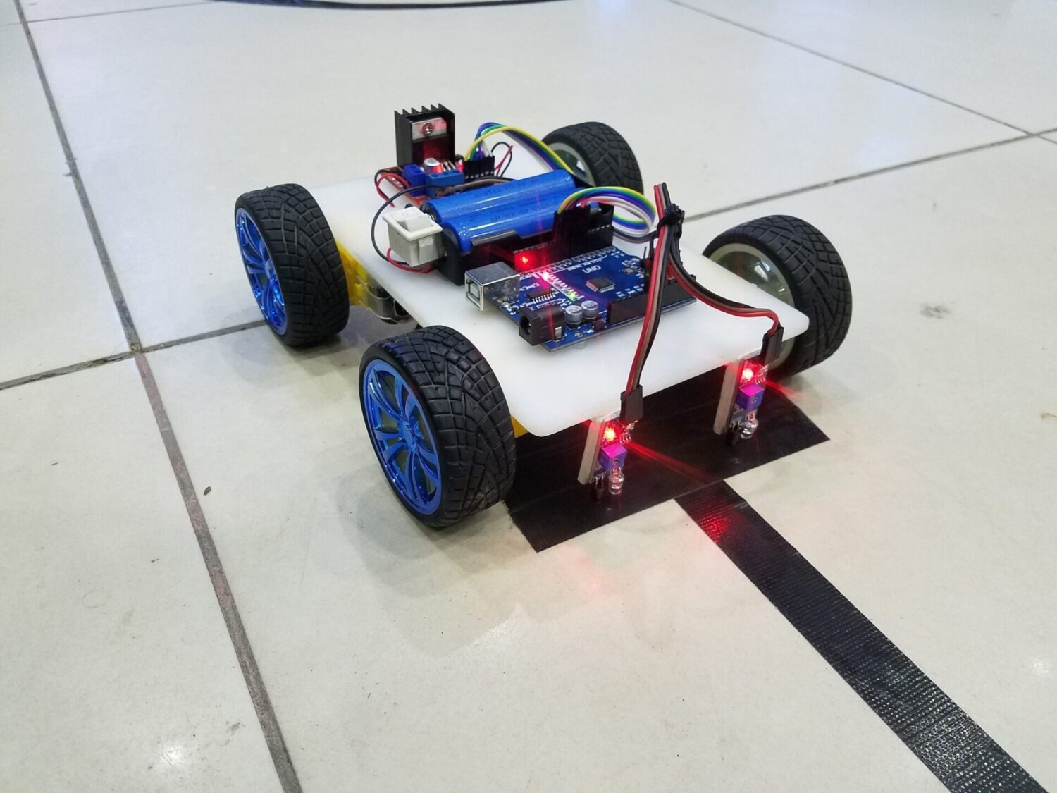
One of the major applications of IR sensors is their usage in sensing the white or black track for line-following robots. Such types of Robots use to follow a certain track to deliver the goods to a destined place. IR sensor through the pin OUT gives either logic 0 or 1. There is a threshold value of voltage. Any value under the threshold considers to be logic 0 and anything above that consider being logic 1. For example, if there is a white or black track and a Robot requires to remain on the track then it becomes necessary for the robot to sense that track. IR sensor returns logic 0 or 1 after detecting black or white track.
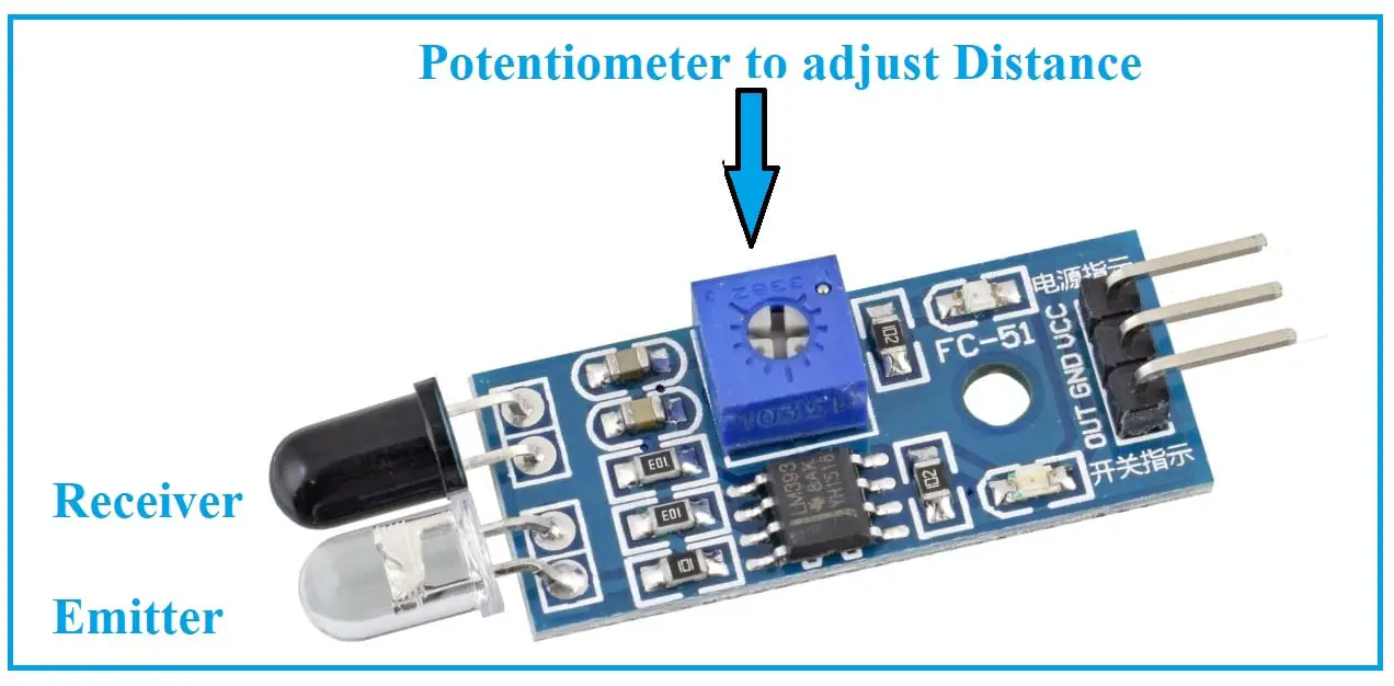
Role of Potentiometer
The potentiometer is present on the sensor for calibration. The threshold value which determines the logic 0 or logic 1 depends on the potentiometer. By rotating the potentiometer, you can calibrate or tune the sensor. In order to get the IR sensors working properly, calibration is important and the potentiometer present on the sensor provides that control to the user.
Pinout of IR sensor
There are three pins on the sensor: 1) Vcc 2) Ground and 3) Out. VCC is a power pin where 5 volts from the microcontroller is provided. GND pin of IR sensor connects with the ground pin of Arduino. OUT pin connects to any digital pins.
| Sr. | IR Sensor pin | Arduino Uno Pin |
| 1 | VCC pin | 5V of Arduino Uno |
| 2 | GND pin | GND pin of Arduino |
| 3 | OUT pin | Pin 2 or any other digital pin of Arduino Uno |
What We Need
As usual, I suggest adding from now to your favourite e-commerce shopping cart all the needed hardware, so that at the end you will be able to evaluate overall costs and decide if to continue with the project or remove them from the shopping cart. So, hardware will be only:
Step-by-Step Procedure
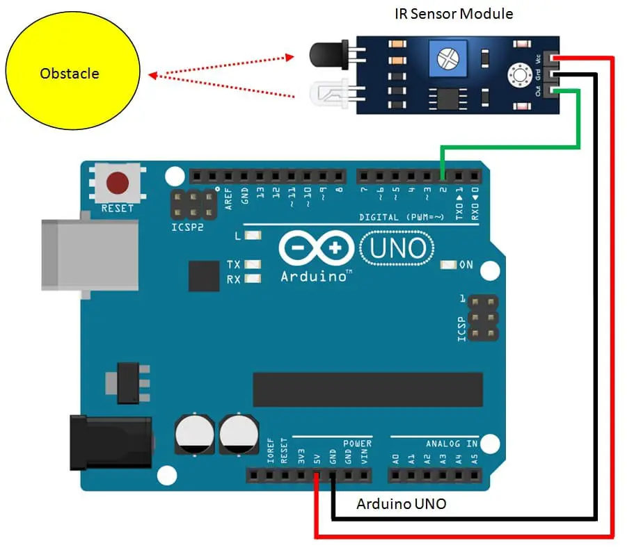
Wiring Diagram
Please prepare wiring according to the following picture.
There are three pins for IR Sensor, Starting from the right side, pin 1 is VCC which needs to connect with VCC. Pin 2 is a GND that connects to the GND of Arduino. Pin 3 is the OUT wire to Arduino pin 2:
Get the IR Sensor Code
Connect your PC to Arduino and open Arduino IDE. For the very first steps, you can refer to Connecting Windows PC with Arduino tutorial. You can get the .ino code from my download area with the following link:
Code Explanation Step by Step
The required code is really simple as IR logic is already built into the IR Sensor.
In the beginning, we declare the ir_sensor_pin with the number of Arduino pin we’ll use. Then in the setup function, we set this pin as an input.
int ir_sensor_pin = 2; // IR sensor pin
void setup()
{
  Serial.begin(9600); // Serial monitor at baud rate 9600
  pinMode(ir_sensor_pin, INPUT); // Pin set as input
}
In the loop function, this sensor pin is read. If it returns logic 1 then it means that an object (or white/black line) has been detected. Otherwise, it means that no objects (or lines) have been detected.
void loop() {
  if (digitalRead(ir_sensor_pin)) // if Pin logic is HIGH
  {
    Serial.println("Object detected"); // display on Serial monitor when object detected
  }

  else {
   Serial.println("Object not detected"); // display on Serial when object not detected
  }
}
Enjoy!
Please find more tutorials on Arduino in peppe8o Arduino archives.
Umar Jamil
For any queries and help for work, please contact me at:
Whatsapp: +92-346-661-7017
Email: umarjamil0007@gmail.com

I'm an Electronic Engineer, well-skilled to solve the issues of hardware and software. I do have laboratory which contains unlimited sensors and modules for testing the working. Also, I am experienced in Arduino programming, Android mobile application, microcontroller programming, IOTs and embedded projects. I provide services to control, realize the sensor data in the Mobile Application. For any queries and help for work Contact: Whatsapp:+92-346-661-7017 Email: umarjamil0007@gmail.com
![]()


