
Last Updated on 2nd September 2023 by peppe8o
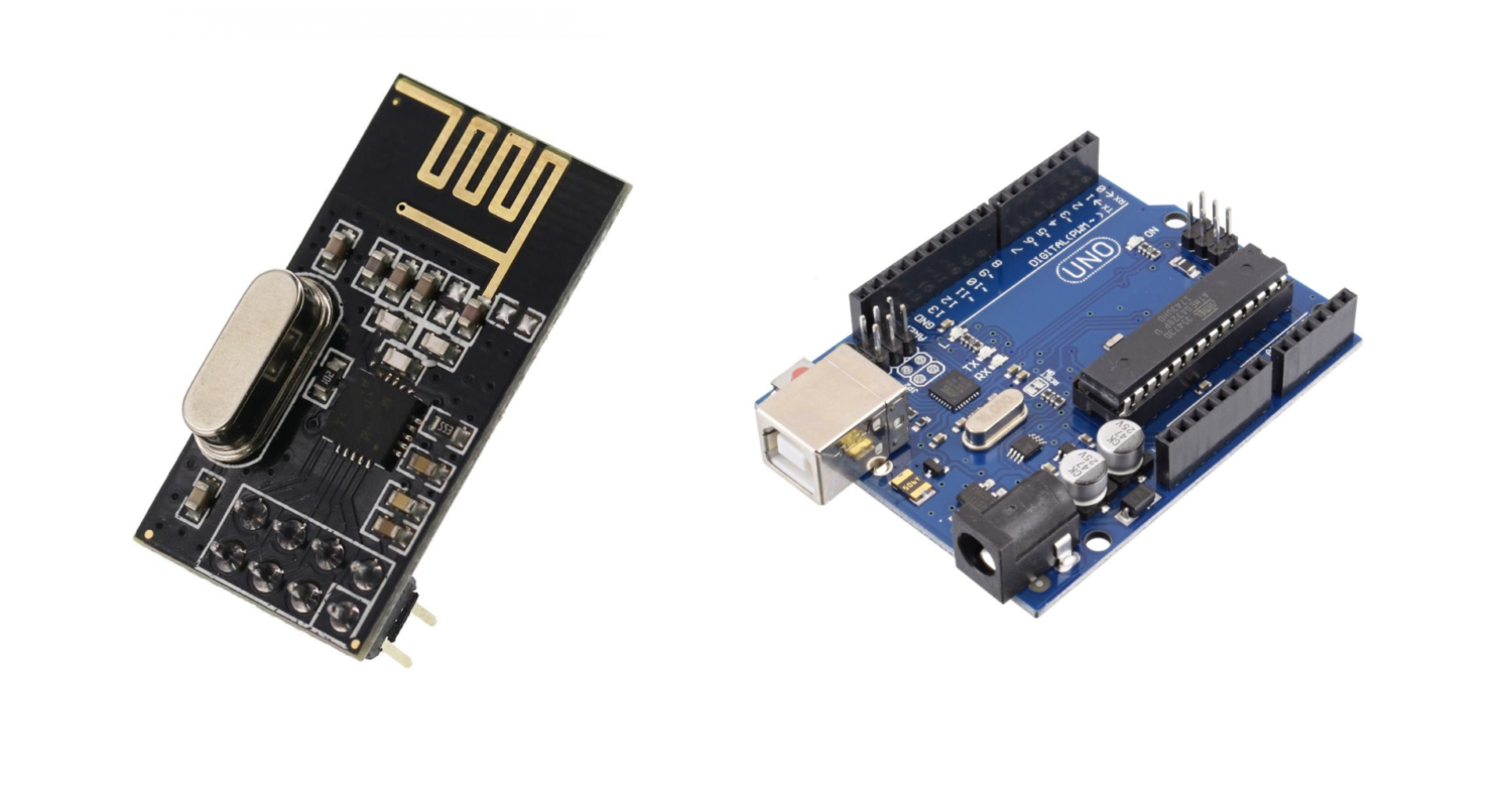
In this tutorial, the nRF24l01 wireless sensor interfaced with Arduino Uno, dealing with RF communication. This tutorial provides the coding, wiring diagram and component list. We’ll learn how to use the nRF24L01 transceiver modules to create wireless communication between two Arduino boards in this article. When utilizing Arduino, the nRF24L01 module is a common choice for wireless communication.
To perform communication wirelessly for a shorter distance, nRF24l01 is best to be used as it has effective speed. The communication with this module is up to 10-meters in the line of sight.
nRF24L01 Introduction
These RF modules are extremely popular among Arduino hobbyists. The nRF24L01 can be found in a wide range of wireless control applications. They are transceivers, which implies that each module has the ability to send and receive data. These modules are extremely inexpensive and may be used with any microcontroller (MCU). The module supports 125 separate channels, allowing for the creation of a network of 125 independently operating modems in one location. Each channel can have up to six addresses, or each unit can talk to up to six other units at once.
Specifications 2.4GHz RF Transceiver nRF24L01
Single-chip technology at a low-cost RF transceiver IC with GFSK at 2.4GHz
Range with antenna: >1000 meters at 250 kbps (open area).
Power Consumption: Extremely low power consumption
3.3V is the input voltage.
5V tolerant pins
Working of NRF24L01
During transmission, the power consumption of this module is just about 12mA, which is even less than a single LED. The module’s operational voltage ranges from 1.9 to 3.6V, but the other pins can handle 5V logic, so we can connect it to an Arduino without requiring any logic level converters. NRF module works in the line of sight, if there is something in the module’s path, then communication will not be that good.
What We Need
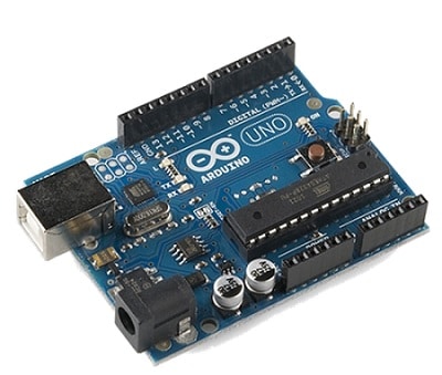
As usual, I suggest adding from now to your favourite e-commerce shopping cart all the needed hardware, so that at the end you will be able to evaluate overall costs and decide if to continue with the project or remove them from the shopping cart. So, hardware will be only:
Check hardware prices with the following links:


Step-by-Step Procedure
Wiring Diagram of nRF24l01 with Arduino
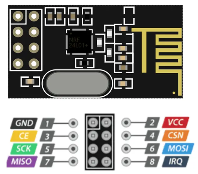
There are 8 pins of the nRF24l01 wireless sensor, VCC connects to the +3.3V, Ground Connect with the GND and OUT connects with the A0 of the Arduino Uno. Other areas are the Serial Peripheral Interface (SPI) pins which I present table to provide clear information. As shown in the image below, the module connects with Arduino Uno. Please follow the wiring that presents in the picture, according to Arduino Uno Pinout:
| Sr. | NRF24L01 pin name | Arduino pin name |
| 1 | GND | GND |
| 2 | VCC | 3.3V |
| 3 | MOSI | 12 |
| 4 | MISO | 11 |
| 5 | SCK | 13 |
| 6 | CE | 4 |
| 7 | CS | 2 |

Get the Slave Code, Master Code and RFcode Library
Connect your PC to Arduino and open Arduino IDE. For the very first steps, you can refer to Connecting Windows PC with Arduino tutorial. You can get the .ino code and libraries from my download area with the following link:
You also need to install the following library, according to my Install Arduino Libraries: methods to add libraries with Arduino IDE tutorial. Please get the zip files from the following link or add it from the available libraries in your Arduino IDE.
Code for Master
This wireless nRF module works on SPI communication. So SPI library is added to enable the communication. Two nRF libraries are added after which CE and CSN pins are declared.
Then we define the pipe’s address. This acts for security purposes: only the user who knows this address can communicate with the Master.
The message defines what the Master is going to send to the slave.
The two commands which play an important role in distinguishing between the master and slave are “radio.openWritingPipe(pipe);”, differently from the slave’s “radio.startListening();“.
The pipeline is opened at the same address for both master and slave. In the loop section, we transmit data to the slave with the command of “radio.write( data, sizeof(data))“.
#include <SPI.h>
#include <nRF24L01.h>
#include <RF24.h>
#define CE_PIN 4
#define CSN_PIN 2
const uint64_t pipe = 0xE8E8F0F0E1LL; // address
RF24 radio(CE_PIN, CSN_PIN);
char data[] = "Message from Master to slave";
void setup()
{
  Serial.begin(9600);
  radio.begin();
  radio.openWritingPipe(pipe);
}

void loop()
{
  radio.write( data, sizeof(data) );
}
Code for Slave
The slave code changes in the following two lines:
- “radio.startListening();“: this makes the slave RF module change to the listening scenario
- “radio.read( data, sizeof(data));“: this command read the data message from the master.
#include <SPI.h>
#include <nRF24L01.h>
#include <RF24.h>
#define CE_PIN 4
#define CSN_PIN 2
const uint64_t pipe = 0xE8E8F0F0E1LL;
RF24 radio(CE_PIN, CSN_PIN);
char data[50] = "";
void setup()
{
  Serial.begin(9600);
  delay(100);
  Serial.println("Receiver");
  radio.begin();
  radio.openReadingPipe(1, pipe);
  radio.startListening();
}

void loop()
{
  if ( radio.available() )
  {
      radio.read( data, sizeof(data));
      Serial.println(data);
    }
    else
  {
    Serial.println("No radio available");
  }
}
Conclusion
NRF module works in the line of sight, if there is something in the path of the module, then communication will not be that good. To increase the distance of this nRF module, please consider using a long antenna. Most of the time, there is not enough power from the microcontroller, or the voltage is fluctuating. in that case, use capacitor between VCC and ground.
What’s Next
Please find more tutorials on Arduino in peppe8o Arduino archives.
Enjoy!
Umar Jamil
For any queries and help for work, please contact me at:
Whatsapp: +92-346-661-7017/ Link
Email: umarjamil0007@gmail.com

I'm an Electronic Engineer, well-skilled to solve the issues of hardware and software. I do have laboratory which contains unlimited sensors and modules for testing the working. Also, I am experienced in Arduino programming, Android mobile application, microcontroller programming, IOTs and embedded projects. I provide services to control, realize the sensor data in the Mobile Application. For any queries and help for work Contact: Whatsapp:+92-346-661-7017 Email: umarjamil0007@gmail.com
![]()


