
Last Updated on 19th April 2024 by peppe8o
In this tutorial, I’m going to show you how works and how to use I2C with Raspberry PI Pico.
I2C (Inter-Integrated Circuit) communication allows to reduce wiring difficulty when connecting devices able to support this protocol. It is widely used in electronics industry and also Raspberry PI Pico can use I2C
Explaining How I2C Works
I2C (pronounced “I squared C”) is a synchronous communication protocol invented in 1982 by Philips Semiconductors. It supports multi-master, multi-slave, packet switched, single-ended, serial communications between supporting devices. I2C allows to connect lower-speed peripheral to processors and microcontrollers.
It uses a simple 2 wire communication bus, Serial Data Line (SDA) and Serial Clock Line (SCL), pulled up with resistors. Typical voltages used are +5 V or +3.3 V.
Master devices generates the clock, so keeping communication management ownership. All devices share same wires:

Common I2C bus connections can work at 100 kbit/s (also known as standard mode) or at 400 kbit/s (known as Fast mode). You can theoretically use also arbitrarily low clock frequencies. On the other side, faster speeds are allowed on more recent I2C revisions, raising speed up to 1 Mbit/s (Fast mode plus), 3.4 Mbit/s (High Speed mode), and 5 Mbit/s (Ultra Fast-mode).
I2C uses basic transactions to let devices communicate between them. Each transaction begins with a START and ends with a STOP signal:
- Single message – Master writes data to Slave
- Single message – Master reads data from Slave
- Combined format – Master sends at least two reads or writes to one or more Slaves
The I2C uses a 7-bit address space to identify each device on the bus and send requests to correct slave listening on the bus.
More info about this communication protocol can be found in Wikipedia I2C page.
Common I2C MicroPython Commands
Micropython includes an I2C class in its “machine” module, which makes it simple using this communication protocol. Common methods are below reported and refer to MicroPython I2C documentation.
- Constructors
- machine.I2C(id, *, scl, sda, freq=400000) – creates a new I2C object
- General Methods
- I2C.init(scl, sda, *, freq=400000) – initialise the I2C bus with the given arguments
- I2C.deinit() – turn off the I2C bus
- I2C.scan() – scan all I2C addresses (between 0x08 and 0x77 inclusive) and return a list of those that respond
- Primitive I2C operations
- I2C.start() – generate a START condition on the bus
- I2C.stop() – generate a STOP condition on the bus
- I2C.readinto(buf, nack=True, /) – reads bytes from the bus and stores them into “buf” variable
- I2C.write(buf) – write the bytes from “buf” variable to the bus
- Standard bus operations
- I2C.readfrom(addr, nbytes, stop=True, /) – read nbytes from the slave specified by addr
- I2C.readfrom_into(addr, buf, stop=True, /) – Read into buf from the slave specified by addr
- I2C.writeto(addr, buf, stop=True, /) – Write the bytes from buf to the slave specified by addr
- I2C.writevto(addr, vector, stop=True, /) – Write the bytes contained in vector to the slave specified by addr (vector should be a tuple or list of objects with the buffer protocol)
- Memory operations
- I2C.readfrom_mem(addr, memaddr, nbytes, *, addrsize=8) – Read nbytes from the slave specified by addr starting from the memory address specified by memaddr (addrsize specifies the address size in bits)
- I2C.readfrom_mem_into(addr, memaddr, buf, *, addrsize=8) – Read into buf from the slave specified by addr starting from the memory address specified by memaddr. The number of bytes read is the length of buf. (addrsize specifies the address size in bits)
- I2C.writeto_mem(addr, memaddr, buf, *, addrsize=8) – Write buf to the slave specified by addr starting from the memory address specified by memaddr (addrsize specifies the address size in bits)
In the following example, I will show you how to use Raspberry PI Pico with I2C, connecting a generic device, and scanning I2C bus to find slave addresses. I will use a generic I2C LCD screen, but this applies to all I2C compatible devices.
What We Need
As usual, I suggest adding from now to your favourite e-commerce shopping cart all the needed hardware, so that at the end you will be able to evaluate overall costs and decide if to continue with the project or remove them from the shopping cart. So, hardware will be only:
- A common computer (maybe with Windows, Linux or Mac). It can also be a Raspberry PI Computer board
- Raspberry PI Pico microcontroller (with a common micro USB cable)
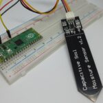
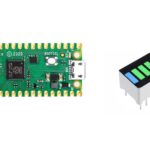
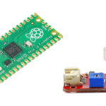
- a generic I2C device (for example a I2C LCD)
Wiring Diagram
The following picture shows how to wire a generic I2C device to Raspberry PI Pico:
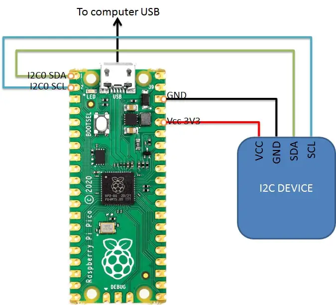
Note that SDA connects to SDA and SCL connects to SCL.
Step-by-Step procedure
Connect RPI Pico to Thonny (you can refer to my tutorial about First steps with Raspberry PI Pico). Download my rpi_pico_i2c_scan.py script on your computer and open it with Thonny.
The following paragraphs will describe my code line by line. At the end, you will find the expected results.
Required modules are imported:
import machineSDA and SCL PINs are defined as variables, set to corresponding PIN numbers:
sdaPIN=machine.Pin(0)
sclPIN=machine.Pin(1)
An I2C instance is set, associated with the variable named “i2c”. This requires the i2c block number (0 – zero, in our wiring). It also requires the SDA and SCL PIN variables and, finally, the bus frequency:
i2c=machine.I2C(0,sda=sdaPIN, scl=sclPIN, freq=400000)The following lines notify the user that scanning is going to start and uses the “devices” variable (a list) to store scan results, which return a list of all device’s address (in decimal):
print('Scanning i2c bus')
devices = i2c.scan()
If no devices have answered, then the devices list will not include any number, so its length will be 0:
if len(devices) == 0:
 print("No i2c device !")
On the other hand, if at least one device answered to scan, then the device length will be equal to the number of devices found:
else:
 print('i2c devices found:',len(devices))
Finally, for each device in the list, its address will be printed (both in decimal and hexadecimal) with a for loop:
for device in devices:
 print("Decimal address: ",device," | Hexa address: ",hex(device))
Running the rpi_pico_i2c_scan Script
Run this script on Thonny (F5 key), selecting “This computer” as Save Location (if requested).
This will output the following:
Scanning i2c bus
i2c devices found: 1
Decimal address:  39  | Hexa address:  0x27
The found address will be useful for your programs to set the correct identifier and send data to the right slave device.
To make the device work, you have now to look for a specific i2c library for that sensor with Raspberry PI Pico and MicroPython. You can search peppe8o.com for Raspberry PI Pico with I2C tutorials, which is growing by the time as I’m adding new guides.
Enjoy!

Open source and Raspberry PI lover, writes tutorials for beginners since 2019. He's an ICT expert, with a strong experience in supporting medium to big companies and public administrations to manage their ICT infrastructures. He's supporting the Italian public administration in digital transformation projects.
![]()
![]()
![]()
![]()
![]()
![]()
![]()

Does the PiPiCo’s I²C support multi-master and slave-mode?
Hi,
it appears so by checking RP2040 docs (https://datasheets.raspberrypi.com/rp2040/rp2040-datasheet.pdf).
Some users have tested (and reported that they were able to) using at least the Pico as multi-slave in this RPI forum post: https://forums.raspberrypi.com/viewtopic.php?t=304074&sid=9308330023dcc395875004cd41c928ea