
Last Updated on 2nd September 2023 by peppe8o
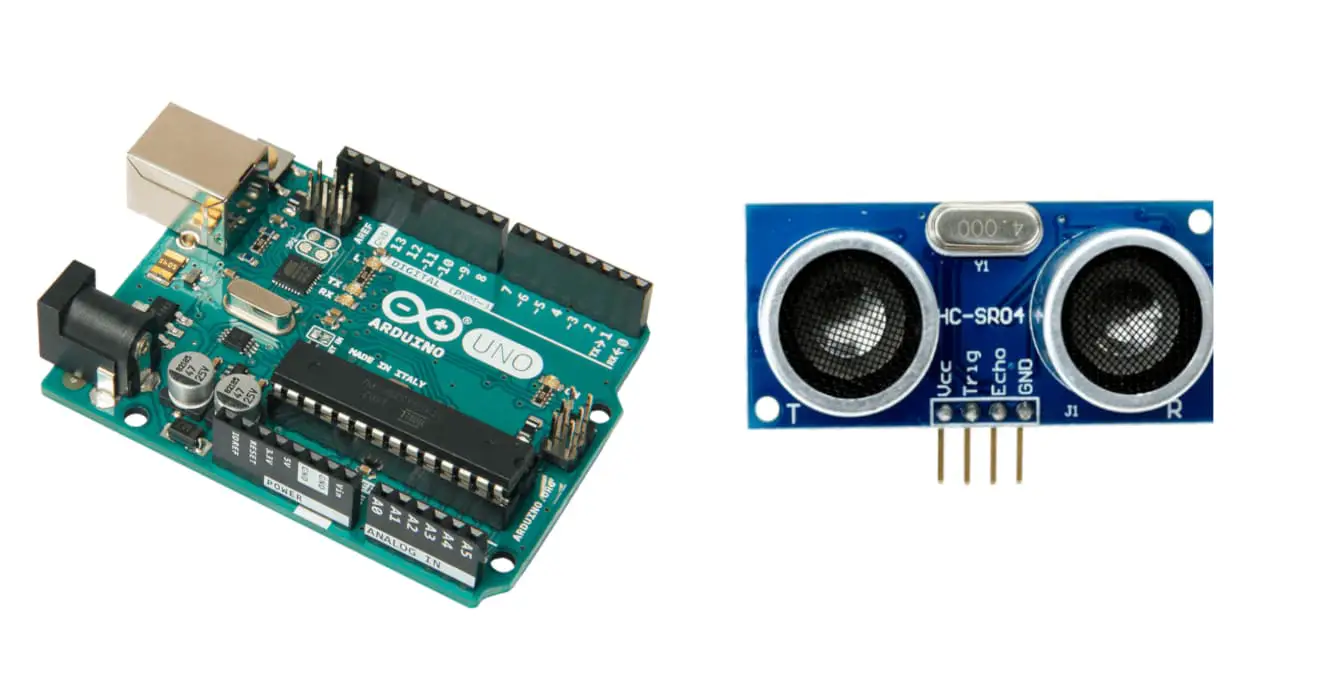
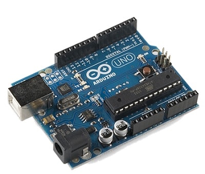
In this tutorial, I’m going to show you how to interface the ultrasonic sensor (HC-SR04) with Arduino Uno. The sensor has the ability to measure distance.
Checking obstacle distance to your robot or, generally speking, to your prototype can give your project the awarenes on how a risk is near and warn the user accordingly to your code. HC-SR04 sensor with Arduino has a particular work principle really interesting and can be coded easily once acquired this knowledge
The HC-SR04 Ultrasonic Sensor
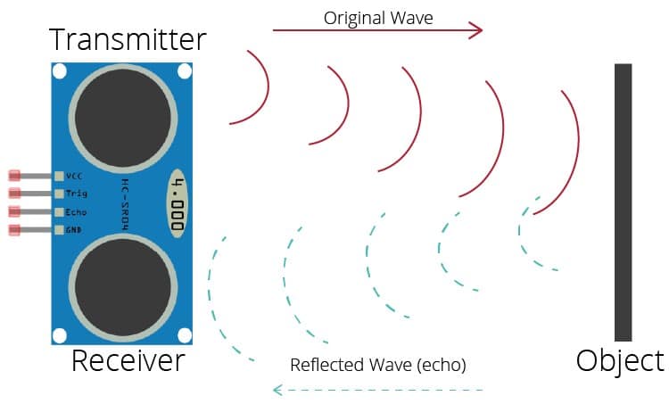
The ultrasonic sensor is a module with the help of which distance calculate. The ultrasonic sensor emits a sound at the frequency of 40 kHz which travels through the air and if there is any obstacle in its way, the wave hits the obstacle and reflects back. As the wave hits back the receiver the value of time note down. The value of time and speed of the travelling wave is known, the value of distance becomes very easy to display.
Features of Ultrasonic Sensor
The sensor requires an input voltage of up to 5 volts. The working current of the ultrasonic sensor is 15 milliamperes. The distance this sensor can measure is in the range of 2cm to 400 cm.
Power Supply: 5 volts
Working Current: 15 milli Amperes.
Distance Range: 2cm to 400cm.
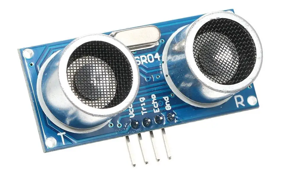
Pinout of Ultrasonic Sensor
The Ultrasonic Sensor is a module consisting of four pins namely VCC, GND, Echo, and Trigger. VCC is a power pin where the microcontroller provides 5 volts. GND pin of ultrasonic sensor connects with the ground pin of Arduino. Digital PINs will control the Echo and Trigger pins.
| No. | Ultrasonic Sensor pin | Arduino Uno Pin |
| 1 | VCC pin | 5V of Arduino Uno |
| 2 | GND pin | GND pin of Arduino |
| 3 | Trigger Pin | Pin 3 or any other digital pin of Arduino Uno |
| 4 | Echo Pin | Pin 2 or any other digital pin of Arduino Uno |
Working Principle
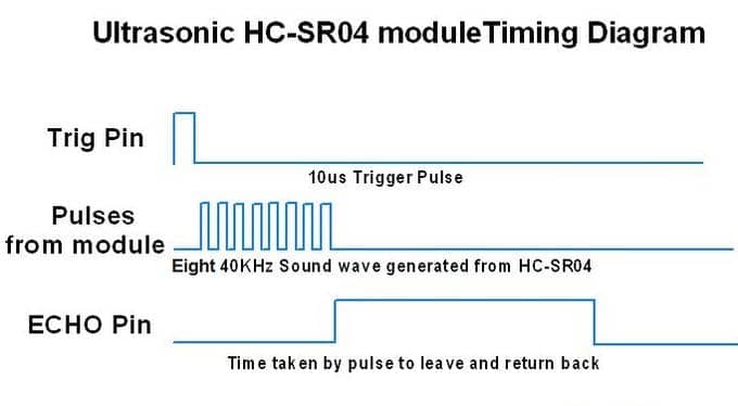
In order to generate ultrasonic sound, the Trigger pin should remain in a HIGH state for a brief amount of time of 10 microseconds. After remaining in a HIGH state for 10 microseconds 8 cycles of sonic burst are sent by trigger pin. These cycle bursts travel through the air at the speed of sound and receive at an echo pin. As soon as the wave arrives at the echo pin, the time travel by the wave calculates in microseconds.
For example, if we get a certain value of time at the echo pin, it will be double the actual value. The reason behind the doubling of the value is that the wave goes and hits the obstacle and then comes back so actually whatever time value note down by the echo pin divides by two. Since the value of the speed of sound is easy and the value of time calculates at the echo pin then calculating the distance becomes easy.
What We Need
As usual, I suggest adding from now to your favourite e-commerce shopping cart all the needed hardware, so that at the end you will be able to evaluate overall costs and decide if to continue with the project or remove them from the shopping cart. So, hardware will be only:
Check hardware prices with the following links:


Step-by-Step Procedure
Wiring Diagram
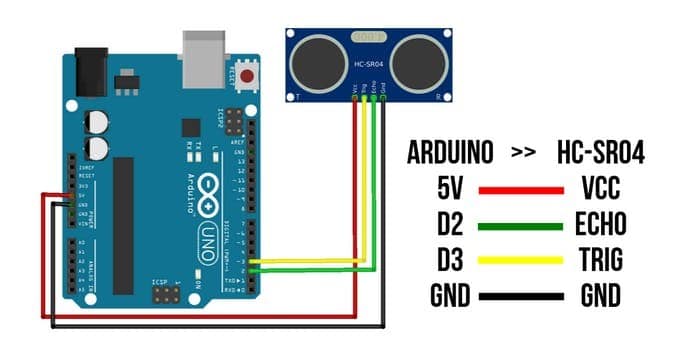
Please connect the HC-SR04 to Arduino according to the following picture. The Ultrasonic Sensor has 4 pins. Starting from the right side, pin 1 is GND (to connect with GND). Pin 2 is an echo that connects to Pin 2 of Arduino. Pin 3 is the trigger (wire to pin 3), and Pin 4 is VCC which should connect to 5V.
Get the HC-SR04 code for Arduino
Connect your PC to Arduino and open Arduino IDE. For the very first steps, you can refer to Connecting Windows PC with Arduino tutorial. You can get the .ino code for HC-SR04 from my download area with the following link:
Open this code in your Arduino IDE.
Ultrasonic Sensor Code Explanation
This section explains the code line by line so that it should be easy to edit according to your needs. In the first two lines, we declare the echo pin and trigger pins to be 2 and 3 respectively. Then in the next two lines, we declare the two variables (duration and distance) that will manage the HC-SR04 according to its timing diagram.
const int trigPin = 2;
const int echoPin = 3;
long duration;
int distance;
In the setup section, we set the echo pin to input while the trigger pin is defined as output. Because the trigger pin sends the wave and echo pin receives it, it is mandatory to declare them output pin and input pin respectively.
void setup() {
  pinMode(trigPin, OUTPUT); // Sets the trigPin as an Output
  pinMode(echoPin, INPUT); // Sets the echoPin as an Input
  Serial.begin(9600); // Starts the serial communication
}
In the loop section, the trigger pin is set high for 10 microseconds. The pulseIn() function calculates the duration. This duration variable contains the value of time taken by the wave to come back to the echo pin after hitting the obstacle. Time taken to reach the obstacle and time taken to reach the echo pin after hitting the obstacle. Now the distance is the actual value of the distance between the ultrasonic sensor and obstacle. Duration divides by 2 and multiplied by the speed of the wave to calculate the distance. Given below is the formula. distance = duration * 0.034 / 2;
void loop() {
  digitalWrite(trigPin, LOW);   // Clears the trigPin
  delayMicroseconds(2);
  digitalWrite(trigPin, HIGH);   // Sets the trigPin on HIGH state for 10 micro seconds
  delayMicroseconds(10);
  digitalWrite(trigPin, LOW);
  duration = pulseIn(echoPin, HIGH); // Reads the echoPin, returns the sound wave travel time in microseconds
  distance = duration * 0.034 / 2;   // Calculating the distance
  Serial.print("Distance: ");   // Prints the distance on the Serial Monitor
  Serial.println(distance);
  delay(400);
}
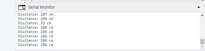
Serial Monitor Output
Here are the distance measurement results from the ultrasonic sensor once set to run. The maximum range of the ultrasonic sensor is 400 cm, it works best for 230 cm, while the minimum range is 20 cm.
Application of Ultrasonic Sensor
The ultrasonic sensor cannot be affected by the presence of light, smoke, or color. There are other sensors for example IR sensor that is greatly affected by light. The ultrasonic sensor has got the advantage of being indifferent to these factors. Now let us see the application of ultrasonic sensors in other fields. Given below are the areas where an ultrasonic sensor is used.
- Obstacle avoidance
- Presence of object
- Level detection
- Distance Measurement
Presence of object: The ultrasonic sensor can use to detect the presence of any person. For example, if there is a room and it is close. The ultrasonic sensor can install in such a way that as soon as any person opens the door an alarm bell rings.
Distance Measurement: one of the most suggestive applications in distance measurement is creating a DIY sonar with the help of a servo motor rotating the HC-SR04 sensor and tracking objects’ distance for every sector.
Enjoy!
Please find more tutorials on Arduino in peppe8o Arduino archives.
Umar Jamil
For any queries and help for work, please contact me at:
Whatsapp: +92-346-661-7017
Email: umarjamil0007@gmail.com

I'm an Electronic Engineer, well-skilled to solve the issues of hardware and software. I do have laboratory which contains unlimited sensors and modules for testing the working. Also, I am experienced in Arduino programming, Android mobile application, microcontroller programming, IOTs and embedded projects. I provide services to control, realize the sensor data in the Mobile Application. For any queries and help for work Contact: Whatsapp:+92-346-661-7017 Email: umarjamil0007@gmail.com
![]()


