
Last Updated on 25th August 2024 by peppe8o
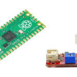
In this tutorial, I’m going to show you how to connect and use an MPU6050 with Raspberry PI Pico and MicroPython.
Gyroscopes and Accelerometers are basic features of modern smartphones. But they are vital for such projects as drones and self-balancing cars. These two kinds of sensor can be achieved with a single chip: the MPU6050. As it can communicate with a I2C interface, you can use it with Raspberry PI Pico.
How MPU6050 Works
The MPU6050 is a Micro-Electro-Mechanical System (MEMS), which are small form factor devices able to convert mechanical movements into electrical signals. The MPU6050 specific case includes a 3-axis accelerometer and a 3-axis Gyroscope (built inside the accelerometer). The accelerometer will measure the acceleration given from a movement (values will be different from zero while it will change its moving speed), while the gyroscope will measure the speed of movement (values will be different from zero while it will move). From this, derives that MPU6050 can measure movement but it will not fit perfectly the aim to define an absolute position. For this purpose, you will need to add a magnetometer as a slave device to MPU6050, by using its auxiliary pins (not explained in this tutorial).
The MPU6050 also includes a temperature sensor, able to give environment temperature. It also includes a (DMP) Digital Motion Processor inside it, which performs complex calculations to send to our Raspberry PI Pico data ready for program use.
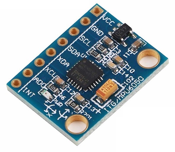
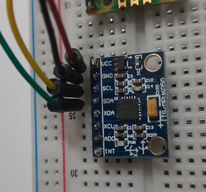
The MPU6050 exposes 8 pins which include Vcc and ground reference, I2C ports, auxiliary system ports, and 2 additional PINS. The following list summarizes its pinout:
- VCC pin is used to power the sensor (supports from 3V to 5V)
- GND pin is connected to the ground source
- SCL (serial clock) pin is a clock pulse pin used for I2C communication (MPU6050 is a slave, so it requires our Raspberry PI Pico to be master, thus providing clock source)
- SDA (serial data) pin transfers data to/from microcontroller according to I2C protocol
- XDA (Auxiliary Serial Data) pin allows connecting external I2C modules with MPU6050 (like, as said, a magnetometer). This pin is optional and MPU6050 can work without any auxiliary device
- XCL (Auxiliary clock) pin enables auxiliary device from MPU6050
- AD0 (Address select) pin is a I2C slave address select pin. This pin allows selecting one of more MPU6050 when connected with a single I2S serial bus
- INT (interrupt) pin is an digital output pin which gives indication to a microcontroller when data are available to be read (also this is optional)
Understanding MPU6050 Axes
Finally, an important consideration when using the gyroscope and accelerometer regarding axes. We know that we have 3 axes for each sensor. These axes use the following convention.
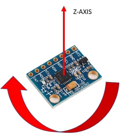
The gyroscope “z” variable measures rotation around an imaginary axis perpendicular to the board (counter-clockwise rotations give positive values). The accelerometer “z” variable measures acceleration along the same axis:
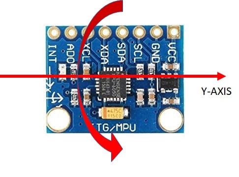
The gyroscope “y” variable measures rotation around an imaginary axis perpendicular to the short side of the board (counter-clockwise rotations give positive values). The accelerometer “y” variable measures acceleration along the same axis:
The gyroscope “x” variable measures rotation around an imaginary axis perpendicular to the long side of the board (counter-clockwise rotations give positive values). The accelerometer “x” variable measures acceleration along the same axis:
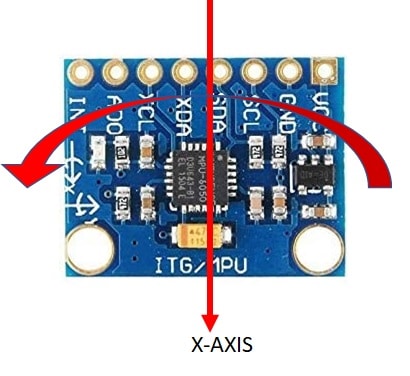
As a simple result of these pictures, an MPU6050 remaining stationary on a desk will have 1 axis (typically the “z” one, but depends on your installation inclination) near to 1, which measures the earth gravity acceleration.
What We Need
As usual, I suggest adding from now to your favourite e-commerce shopping cart all the needed hardware, so that at the end you will be able to evaluate overall costs and decide if to continue with the project or remove them from the shopping cart. So, hardware will be only:
- A common computer (maybe with Windows, Linux or Mac). It can also be a Raspberry PI Computer board
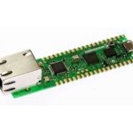
- Raspberry PI Pico microcontroller (with a common micro USB cable)
- MPU6050
- breadboard (optional)
- dupont wirings
Check hardware prices with the following links:


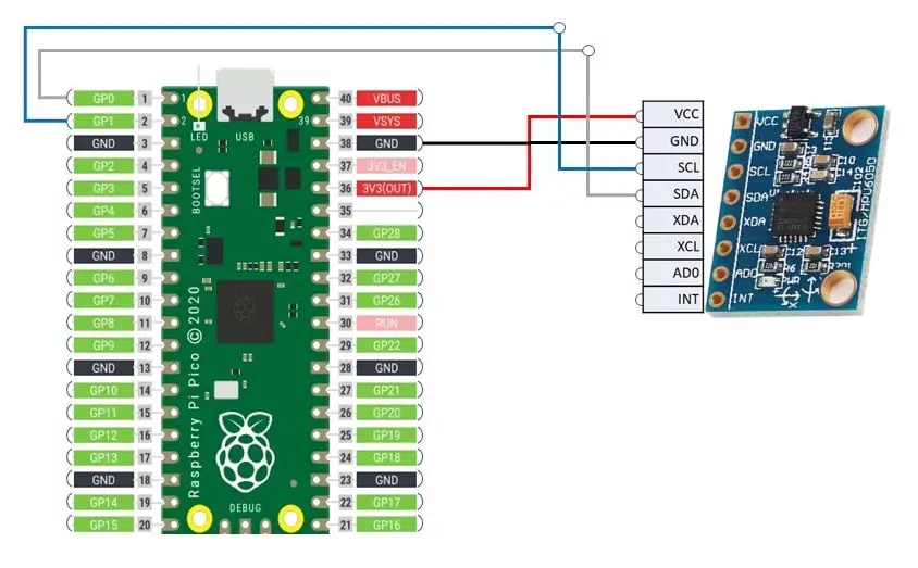
Wiring Diagram
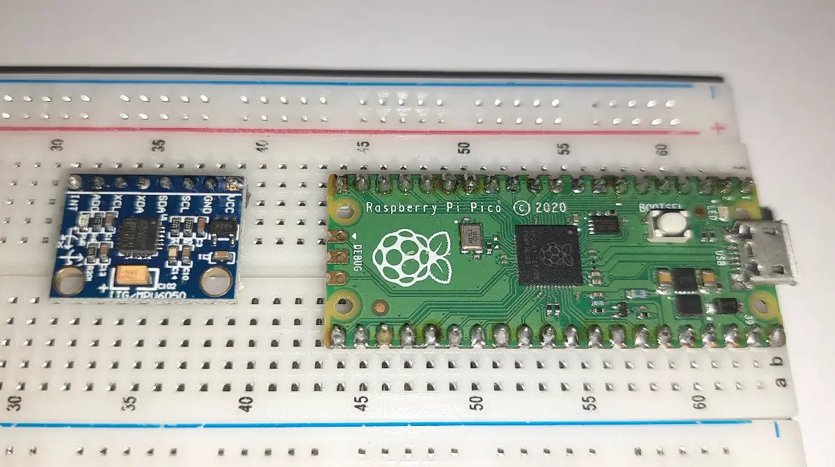
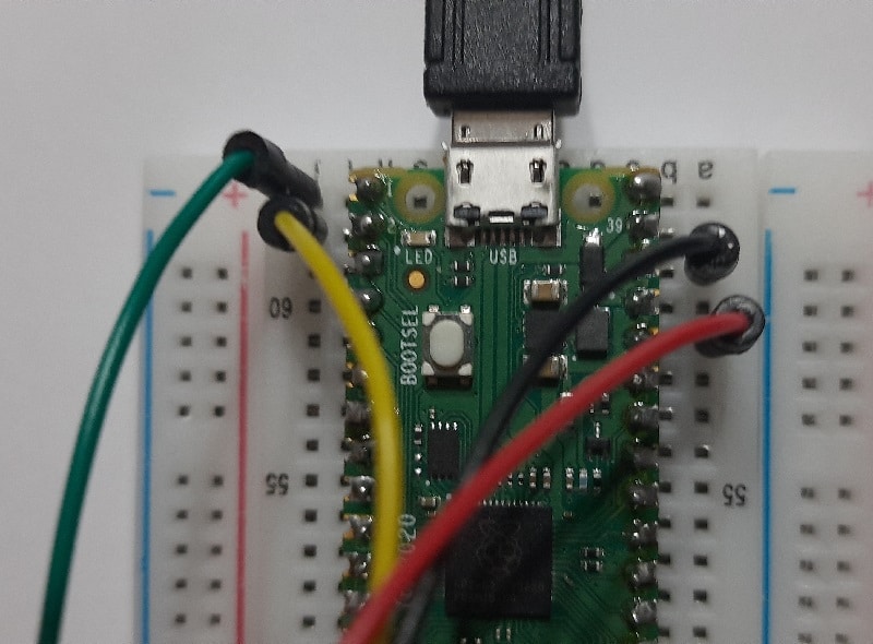
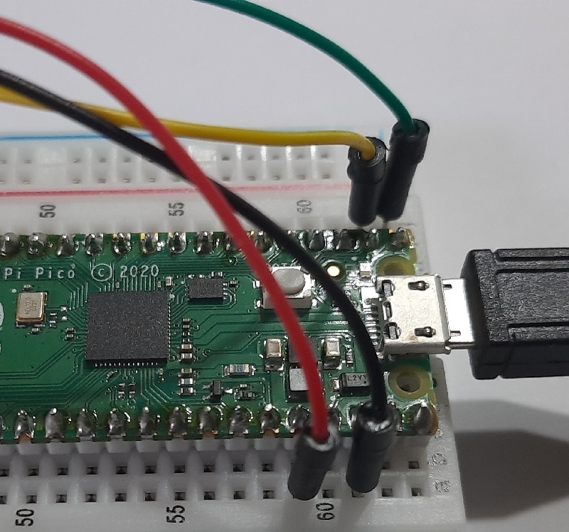
Please find below the wiring diagram:
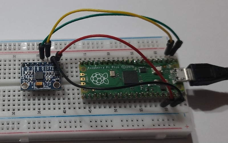
The following pictures better detail my wiring:
Step-by-Step Procedure
Prepare cabling according to the previous paragraph. Connect RPI Pico to Thonny (you can refer to my tutorial about the First steps with Raspberry PI Pico).
Using the common I2C scan procedure (you can find the procedure and code in my Using I2C devices with Raspberry PI Pico and MicroPython tutorial), you will probably find that your MPU6050 address will be 0x68 (in hexadecimal) and 104 (in decimal). If you get a different value (a really hard event), you will probably need to set your address in the following “imu.py” file.
Get MPU6050 MicroPython Libraries
Required libraries are not developed by me, but we’ll use the ones available from GitHub at https://github.com/micropython-IMU/micropython-mpu9x50. You will need to get the “imu.py” and “vector3d.py” files. You can also get a copy from my download area with the following links:
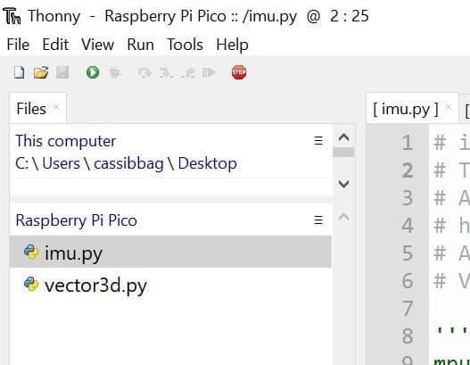
According to my Adding external modules to MicroPython with Raspberry PI Pico tutorial, add these 2 files in your Raspberry PI Pico root folder or inside a folder named “lib”. This will be what appears in my RPI Pico storage:
Get and Understand my picoMPU6050.py Code
Download my picoMPU6050.py file. This will be described in the following paragraphs.
First of all, required libraries are imported. The vector3d.py libraries will be call from impu.py, so there’s no need to import it from here:
from imu import MPU6050
import time
from machine import Pin, I2C
The MPU6050 class requires an I2C object. You can generate it by passing an I2C session activated. Then returned object (which has all the MPU6050 properties) will be associated to an “imu” variable:
i2c = I2C(0, sda=Pin(0), scl=Pin(1), freq=400000)
imu = MPU6050(i2c)
That’s all required to setup our gyroscope and accelerometer! The next part will simply print values get from our device.
We’ll use a while loop to read MPU6050 values from Raspberry PI Pico unless you stop the script. With my code, you can get 2 print formats. The first one lets you see raw data coming from the MPU6050 library, while the second one makes it a bit prettier for human reading.
The raw data printing, which comes after the while statement, has been commented in my script but you can uncomment when needed:
while True:
    #print(imu.accel.xyz,imu.gyro.xyz,imu.temperature,end='\r')
For the second print way, I firstly use the round function to reduce decimal digits. As you can see, you can use accelerometer/gyroscope single values by calling “imu.accel.x” or “imu.gyro.x” (valid for each axis):
    ax=round(imu.accel.x,2)
    ay=round(imu.accel.y,2)
    az=round(imu.accel.z,2)
    gx=round(imu.gyro.x)
    gy=round(imu.gyro.y)
    gz=round(imu.gyro.z)
    tem=round(imu.temperature,2)
Then we’ll print “pretty” values to Thonny shell:
print(ax,"\t",ay,"\t",az,"\t",gx,"\t",gy,"\t",gz,"\t",tem," ",end="\r")
If you need to use only raw data, you can just comment my file rows from ” ax=round…” to the previous print statement, uncommenting the original print row.
A final sleep time (which is a wait command) will let values change less rapidly to make possible for human read them before changing:
time.sleep(0.2)Running the picoMPU6050.py Script
Run this script in your Thonny IDE (F5) and you will start reading measures from MPU6050 in your Thonny shell, as in the following:
MicroPython v1.15 on 2021-04-18; Raspberry Pi Pico with RP2040

Type "help()" for more information.
>>> %Run -c $EDITOR_CONTENT
0.02 	 -0.01 	 0.93 	 -3 	 1 	 -1 	 26.76
When using these values, please consider that:
- MPU6050 has about a +/-3% of accuracy limits, so your program will need to be ready to accept from -3% to +3% of error
- MPU6050 may some seconds stabilize its values. Some users from internet write about 40s should be enoght safe to get stable measures
- MPU6050 may need ,calibration to get real zeros on axes. This means measuring values for a defined time (having the device on a stationary place) and adding an offset to single measures, equal to values measured)
What’s Next
Interested to do more with your Raspberry PI Pico? Try to look at my Raspberry PI Pico tutorials for useful and funny projects!
Enjoy!

Open source and Raspberry PI lover, writes tutorials for beginners since 2019. He's an ICT expert, with a strong experience in supporting medium to big companies and public administrations to manage their ICT infrastructures. He's supporting the Italian public administration in digital transformation projects.
![]()
![]()
![]()
![]()
![]()
![]()
![]()

Thank you for this tutorial!
I have a question though, how do I calculate the tilt angle of the sensor with the raw data?
I’ve been searching for a tutorial for this for months! This is the first one that made sense and worked first time. Thank you so much! 😀
Now, how can I control a servo with the gyroscope data?
I need to create a tilt controlled servo that goes in a model rocket, so when the rocket tilts over at apogee the sensor triggers the servo and opens a parachute hatch.
Can you help?
Hi Glendon,
thank you for your feedback. For your project, I would check the “z” axis acceleration: while it is at its max value, probably you are still at the rising phase. When the Z acceleration goes lower than 0.9, then you probably reached the top altitude and your rocket is starting its falling phase. But this is only in theory, the practice is always the only correct certainty 🙂
Great tutorial. Many thanks.
Thank you for your feedback, Marcus